ASTRAL®
A20-Nexus
8-, 12-, and 16-Channel, True-Diversity Receiver
with SpectraBand Technology
User Guide v1.60
Table of Contents
NexLink Wireless Transmitter Control 4
Navigating the A20-Nexus User Interface 20
RTSA (Real Time Spectrum Analyzer) 32
Antenna RF Overload Indication 40
Frequency Band Restrictions 66
The A20-Nexus is an ultra-high performance, 8-, 12-, and 16-channel wireless microphone receiver in a compact ½-rack wide chassis. It features 8 independent, true-diversity channels which can be expanded to 12 or 16 true-diversity channels via software license. The A20-Nexus features NexLink, an innovative concept in wireless microphone receivers: full remote control of microphone transmitters via an integrated, long distance RF link.
The A20-Nexus can be mounted in a standard 19-inch rack or easily placed remotely near the microphone transmitters due to its ability to be powered by Power-over-Ethernet (PoE+), its Dante audio-over-IP, and built-in web server for control via phone, tablet, or computer.
Additionally, the A20-Nexus can be docked to Sound Devices 833, 888, or Scorpio mixer-recorders using the A20-QuickDock accessory, which provides convenient power, audio, and timecode connections with no additional cables. This accessory allows the A20-Nexus to connect and disconnect from the 833, 888, or Scorpio in seconds with no tools, and be remote mounted when desired.
Our friendly and knowledgeable support team, based in the USA and the UK, is here for all your questions and comments.
The A20-Nexus incorporates SpectraBand, a technology that enables the A20-Nexus to tune over a super wide range of 169-1525 MHz. Tuning within this range varies by country.
For instance:
In the USA, the available frequency ranges are:
In the UK, the available frequency ranges are:
Please see https://www.sounddevices.com/available-frequencies/ for further detailed information on which frequency ranges are available for each country.
Tuning Bands
SpectraBand’s 169-1525 MHz range is divided into multiple, tightly-filtered tuning bands. The sharp attenuation at either end of a tuning band’s range significantly reduces out of band interference resulting in excellent range performance.
Long Range and Standard Modulation
The A20 wireless products offer two proprietary digital modulation schemes that provide unbeatable range, unrivaled audio quality, and very low latency. Long Range or Standard modulation can be selected on a per-receiver-channel basis. Long Range modulation has better sensitivity which results in better range. The modulation setting must match between the A20 transmitter, A10-TX and the A20-Nexus in order for the transmitted signal to be received and decoded.
Intermodulation Immunity
Because the A20 and A10 digital RF transmission is inherently resistant to intermodulation, multiple A10 and A20 Digital Wireless systems can be used simultaneously on nearby adjacent frequencies without significant worry of intermodulation interference. Systems can be used together when separated by at least 400 kHz. When operating in the 902-928 MHz Band, it is recommended to separate channel frequencies by at least 1 MHz.
NexLink is a proprietary 2.4 GHz bidirectional wireless data link technology that allows multiple A20 transmitters to be controlled, monitored, and timecode synced from an A20-Nexus over long distance. NexLink is designed to offer robust and reliable control over distances far exceeding that of the wireless audio transmission, even in the presence of Wi-Fi and Bluetooth interference. An A20-Nexus can pair with up to 64 NexLinked transmitters.
The A20-Nexus supports the A20 transmitter’s GainForward feature. GainForward eliminates the need to adjust microphone preamplifier gain at the wireless transmitter. Audio levels from the transmitter are controlled either directly from the 8-Series (or any other mixer) trim controls, or from the A20-Nexus receiver screen. If the talent speaks too softly or emotes too loudly after being “wired” with the transmitter, simply adjust the transmitter gain with the mixer’s gain trim, instead of having to access the actual transmitter. Read more about GainForward at: https://www.sounddevices.com/gainforward-explained/
When an A20-Nexus receiver channel is receiving signal from an A20 transmitter, adjust the receiver channel’s gain, low cut, and polarity from its associated 1RX view.
When the A20-Nexus is docked on an 8-Series, the Nexus’s gain, low cut, and polarity settings are bypassed and hidden. In this case, adjust the 8-Series’ trim, low cut and polarity gain as necessary. See the 8-Series User Guides for more information.
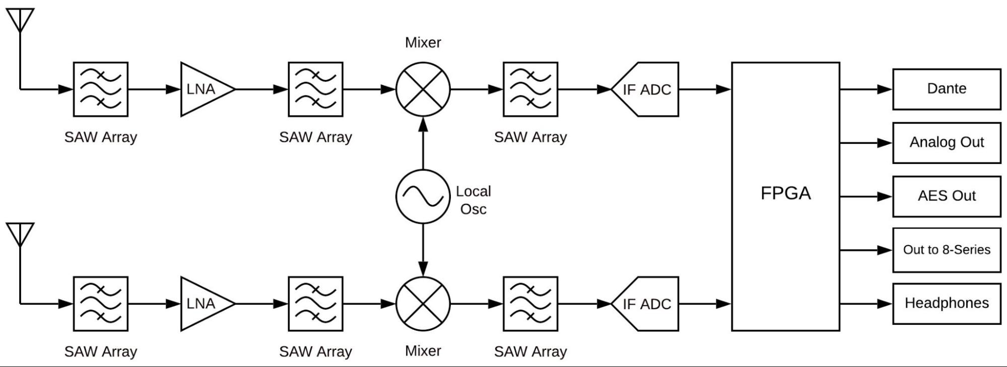
The A20-Nexus takes a brand new approach to professional audio receiver design. The A20-Nexus combines several technologies resulting in a very powerful and versatile product.The diagram below illustrates the architecture of the A20-Nexus.
The first thing to note about the architecture is that there are two entire signal paths. This performs the True Diversity reception inherent in the design. This is a lavish proposition, as it doubles the circuitry, but it is absolutely the best way to perform spatial diversity - superior to any type of antenna or phase diversity.
The first section that comes right after the receive antennas is the first SAW filter array. This pre-select filter is a key element of our unique SpectraBand technology. It allows for a tuning range from 169 MHz - 1525 MHz which is divided into multiple, tightly-filtered tuning bands. The extremely sharp attenuation at either end of a tuning band’s range significantly reduces unwanted interference outside the selected tuning band resulting in excellent range performance. Tuning bands vary in width, but tend to be around 24 MHz wide.
Next is the Low-Noise Amplifier (LNA), which is one of the most important stages in the design. This section has been specially designed for very low noise and high dynamic range, which results in long-range reception and high overload capability. This LNA stage exhibits a noise figure of only 0.35 dB, one of the very best on the market currently.
This is followed by yet another SAW filter array. This array further attenuates out-of-band signals, ensuring reliable reception, and greatly suppressing any image frequencies.
The Local Oscillator and Mixer perform the traditional function of a single downconversion superheterodyne radio. This section has been meticulously designed and is the other key element of our unique SpectraBand technology. This section exhibits extremely low phase noise and wide dynamic range to accurately downconvert the RF to a lower Intermediate Frequency (IF) for conversion into the digital domain.
Before conversion into the digital domain, the signal passes through its final array of SAW filters, rejecting any extraneous energy not wanted in the downconversion, as well as providing anti-aliasing before the Analog-to-Digital (A/D) converter. The A/D converter is a wideband, extremely high dynamic range part which accurately captures 24 MHz of IF energy into a digital version of that signal.
The real magic of the entire A20-Nexus happens within the Field-Programmable Gate Array (FPGA). An FPGA is essentially a giant custom, massively-parallel processor programmed in house. The FPGA can perform filtering, frequency conversion, and demodulation in the digital domain which far exceeds anything that can be done via analog or traditional digital circuitry. The FPGA can perform demodulation of 16 channels simultaneously. The FPGA also performs the True Diversity operation which not only selects the best digital word from the two antennas but actually works at the bit level for additional range. The resultant audio signals are then fed out of the FPGA to the various audio outputs.
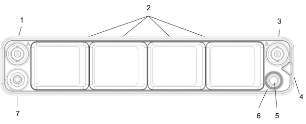
Front Panel
1 & 3: Antenna Connector A & B
BNC connectors, for connecting to active, passive, or smart antennas.
2: Touch Screens
Color OLED array for control and monitoring.
4: Triangle Button
5: Control Knob
6: Multicolor Ring LED
7: Headphone Output
3.5 mm connector
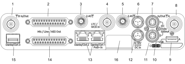
Rear Panel
1 & 8: Antenna Connector A & B Inputs / Cascade Outs
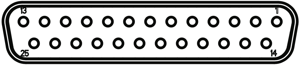
2 & 14: Top & Bottom D-Sub Audio Output Connectors
25-pin D-Sub connectors for outputting analog (mic/line/guitar level) or AES digital. See menu (Main Menu>Audio Output). Disabled when mounted to an 8-Series via the expansion port. Note: the pin-out follows the AES59 standard. The analog output pin-out is different from the AES digital output pin-out. See Connector Pin Assignments section for more information.
3 & 5: 2.4 GHz Antenna Connectors
Dual SMA-F ports for connecting 2.4 GHz SMA-M antennas for NexLink. Both antennas need to be connected.
Important: Only use the 2.4 GHz SMA-M antennas supplied with the A20-Nexus or equivalent. Do not use 2.4 GHz RP-SMA antennas such as those used for the 8-Series bluetooth antenna.
4: LTC / Wordclock Input
BNC for connecting LTC or Wordclock input. Nexus auto-detects whether the signal is LTC or Wordclock including the associated frame rate or sample rate. Disabled when mounted to an 8-Series via the expansion port.
6 & 12: DC Inputs
Dual TA4-M, 10-18V DC inputs. Highest voltage takes precedence. Disabled when docked to an 8-Series via the expansion port.
7 & 11: DC Outputs
Dual, 4-pin Hirose female DC outputs (500 mA max between both outputs) for powering IFB transmitters, camera hops, and other low power peripherals. Disabled when docked to an 8-Series via the expansion port.
When powered via TA4, voltage is passed through from the DC input (10-18V). When powered via PoE+, DC Outputs supply 12V DC.
9: USB-A Port
Multi-function USB-A port for:
Tip: The USB-A port supports USB hubs so that multiple devices can be connected at the same time. Maximum power output of 2.5 Watts (5V, 500 mA)
10: USB-C Port
For factory use only.
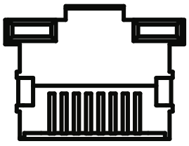
13: Ethernet Ports 1 & 2
2x RJ45 ports for Dante and/or Control. Nexus can be powered via PoE+ (minimum 25W) via port 1. Dante is disabled when docked to an 8-Series via the expansion port. Control remains enabled.
15: SFP Port
Accepts a wide variety of Small Form-factor Pluggable (SFP) modular network transceivers, including optical fiber options for Ethernet Dante and/or Control connection. Dante is disabled when docked to an 8-Series via the expansion port. Control remains enabled.
16: Factory Access Cover
Covers and protects the factory-use only ports.
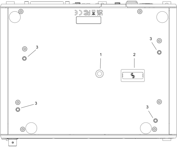
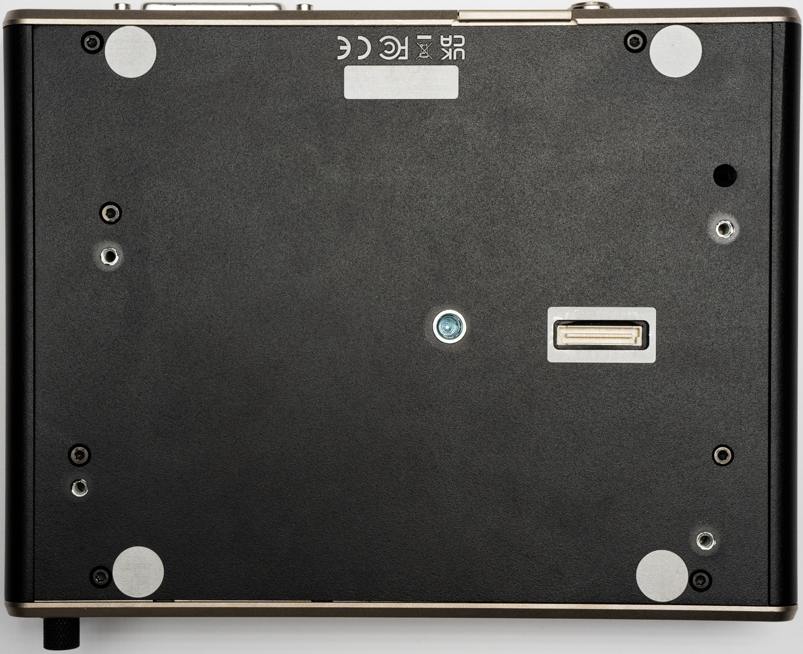
Bottom Panel
1: Mounting Point
1 / 4”, 20 screw hole for mounting purposes.
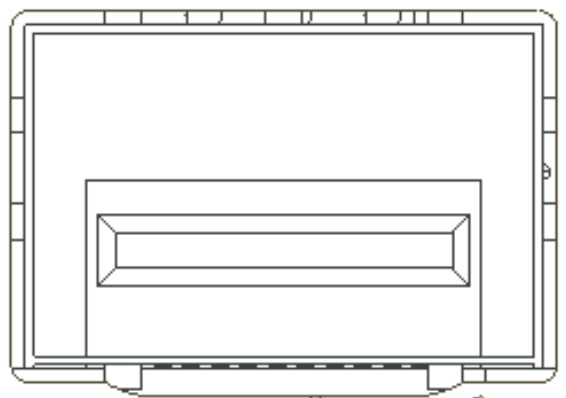
2: Expansion Port
For docking A20-Nexus to an 8-Series mixer/recorder using the A20-QuickDock optional accessory.
The expansion port provides power from the 8-Series and passes the multichannel receiver digital audio signals from A20-Nexus to the 8-Series. When docked on an 8-Series:
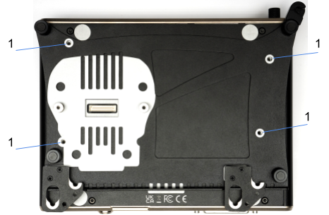
3: Screw holes for A20-QuickDock and A20-Shelf
Four screw holes for mounting the A20-Nexus to an A20-Shelf and A20-QuickDock
The versatile A20-Nexus can be used in many types of setup and workflow. This section details just a few examples.
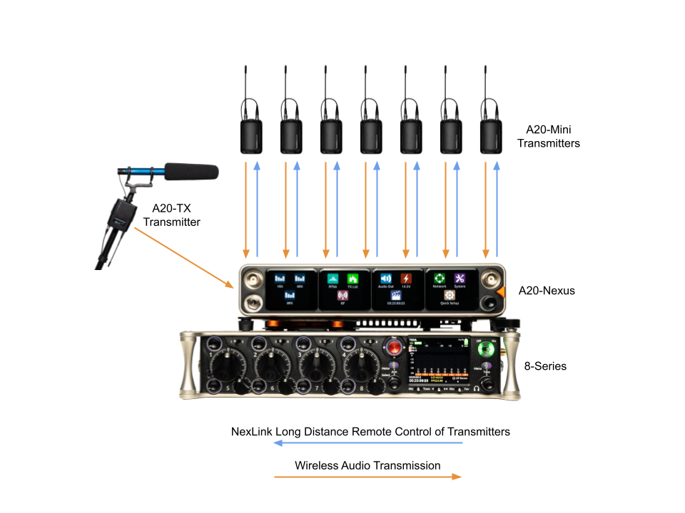
1. Bag Setup: Nexus docked to an 8-Series Mixer-Recorder
The A20-QuickDock accessory enables the A20-Nexus to be docked to an 8-Series mixer-recorder. The bottom panel incorporates a multi-pin expansion port that connects power from the 8-Series and passes the multichannel receiver digital audio from A20-Nexus to the 8-Series.
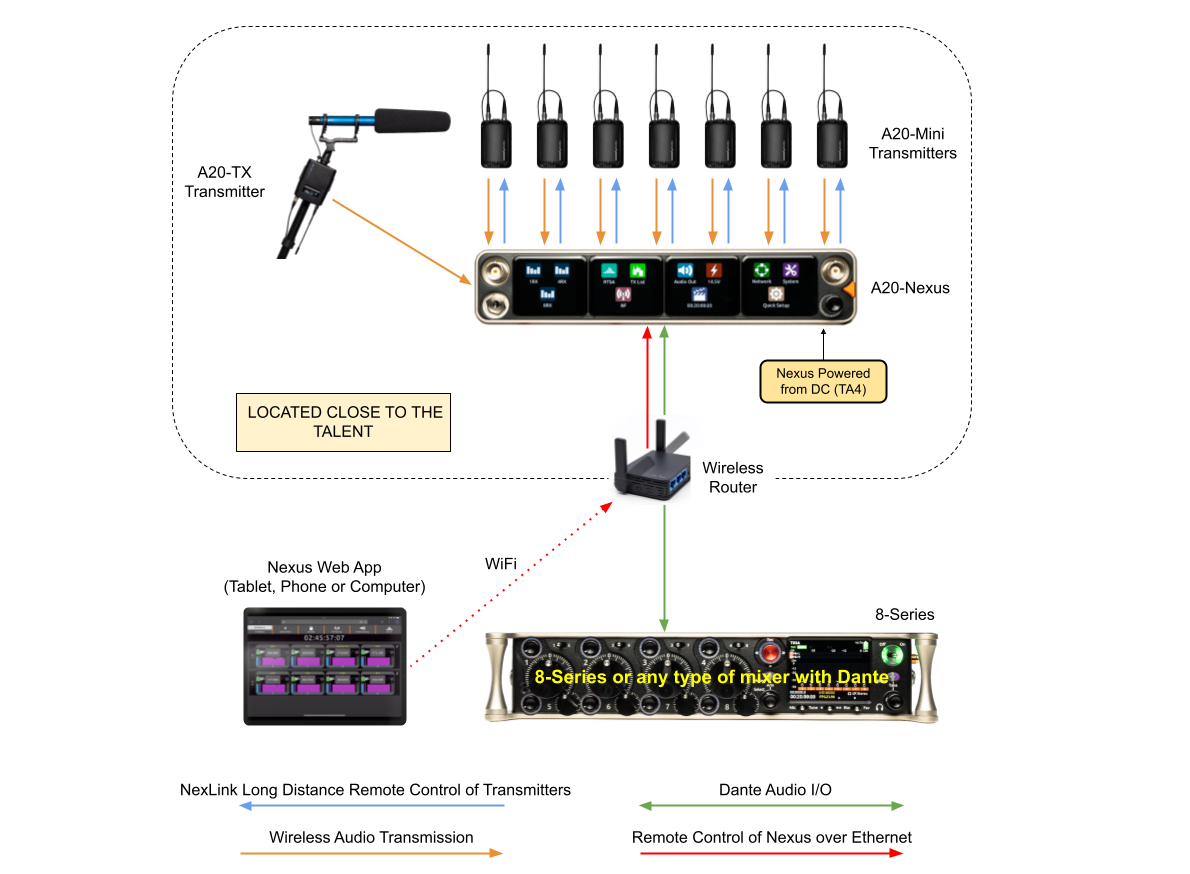
2. Remote Setup: Nexus located on set, close to talent
Remotely locating the A20-Nexus multichannel receiver close to talent significantly reduces the chance of RF dropouts since the distance between those wearing the transmitters and the A20-Nexus receiver is minimized. A single CAT cable can be used to transport Dante audio and remote control data between Nexus and the sound mixer. As well as sending Dante audio to the mixer, the Nexus can also receive Dante audio back from the mixer, useful for distributing VoG and/or IFB feeds etc via its analog D-Sub outputs. In this example, the Nexus Web App is running on a tablet and controlling the Nexus over Wi-Fi.
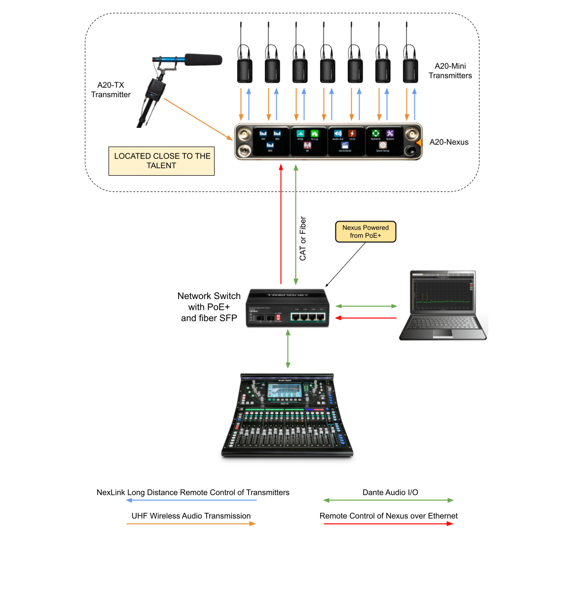
3. Remote Setup: Nexus located on set, close to talent, powered from PoE+
Similar to the previous setup, but with the Nexus being powered over PoE+. In this example, a computer is controlling Nexus via the Web App and is also sending and receiving Dante to and from Nexus.
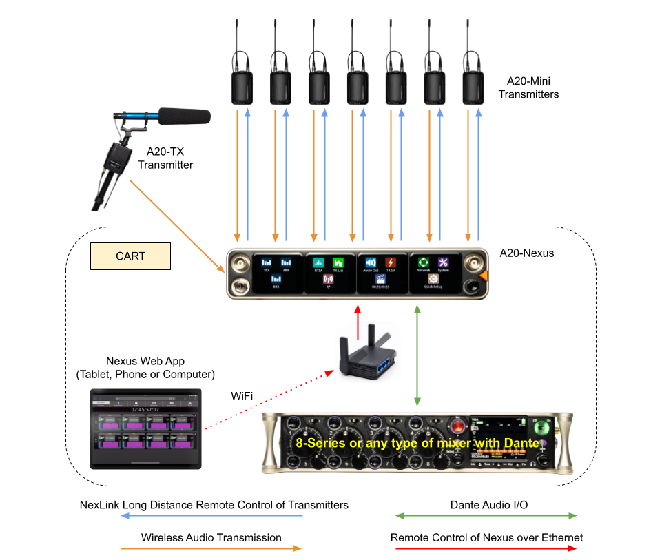
4. Cart Setup
A typical cart setup with Nexus. As well as sending Dante audio to the mixer, the Nexus can also send audio from its AES or Analog D-Sub outputs. In this example, the Nexus Web App is running on a tablet and controlling the Nexus over Wi-Fi.
This Quick Start guide assumes that the A20-Nexus is being used as a standalone receiver.
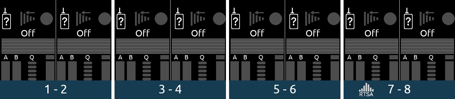
8RX View
Main Menu
RF Menu
Antenna Settings
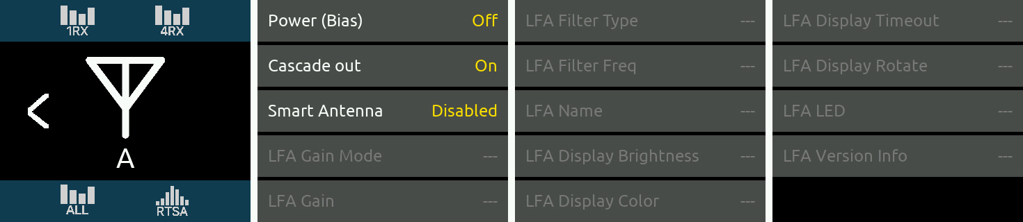
The antenna icons will show a lightning bolt icon next to them when bias power is enabled.
Note: A10-TX transmitters cannot be paired or NexLinked with the A20-Nexus.
From the Main Menu, tap the TX List icon.
To pair an A20 transmitter, ensure it has a charged battery or batteries installed, then connect its USB-C port to the A20-Nexus USB-A port. The A20 transmitter will appear in the TX List after a few seconds. The A20-Nexus will then automatically establish a NexLink connection between the transmitter and the next available receiver channel. This can take up to a minute or so. Once connection is established, the NexLink RSSI icon is displayed in the TX List > NexLink column.
TX List
1RX View
Tip: Before assigning frequencies, it is highly recommended to perform a scan of the local RF environment using Scan Mode to identify and choose a clear Tuning Band. See RTSA > Scan Mode for further information.
Congratulations! You have your first wireless channel ready to go.
The A20-Nexus is powered from TA4 (10-18 VDC), PoE+, from the 8-Series (via expansion port), or via XL-WPTA4
AC mains adapter (purchased separately).
The control knob ring LED illuminates blue during power up, then goes out once fully booted.
When the Nexus is first powered on, the last accessed RX View is displayed.
Tip: Reducing A20-Nexus power consumption:
Powering when Nexus is operated standalone (not docked to an 8-Series)
Connect a 10-18 VDC power source (20 watt minimum) to the TA4 DC power inputs and/or PoE+ power source (30 watt minimum) to ethernet port ‘Dante/Ctrl 1’. Connecting multiple power sources allows for redundancy since the A20-Nexus seamlessly switches between power sources should one fail. The power source with highest voltage takes precedence and is displayed along with its voltage beneath the Power menu icon in the Main Menu and in screen 1 of the Power menu.
Powering when Nexus is docked to an 8-Series
Connect power to the 8-Series. Power is supplied to the Nexus from the 8-Series expansion port.
Note: When docked, powering via the A20-Nexus TA4 or PoE+ power inputs is disabled.
Ensure that the 8-Series System Menu > Expansion Port is set to On.
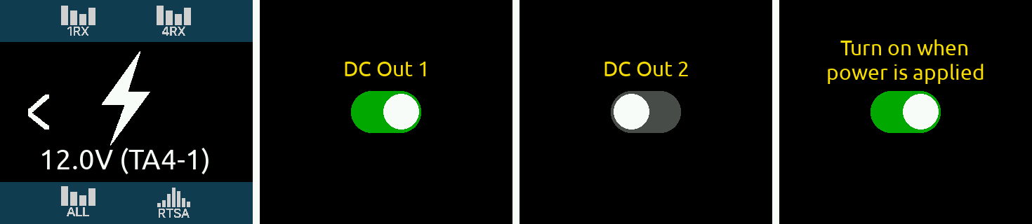
Power Outputs DC Out 1 and DC Out 2
The DC Outs can be used for powering IFB transmitters, camera hops, and other low power peripherals.
Enable or disable each DC Output from the Power menu.
The A20-Nexus is operated from its front panel triangle button, control knob, and four touch screens or remotely via its web interface.
Triangle Button
Control Knob
Touch Screen UI Elements
The A20-Nexus uses a number of different UI elements for changing settings i.e. toggle switch, list button, value button, action button, etc.
Note: When any touch screen UI element is selected, brightness is reduced and touch is disabled on all other touch screens.
Off
On
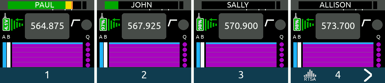
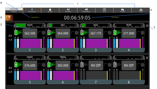
RX Views display real-time receiver channel, transmitter signals, and status information across the four touch screens.
There are several types of RX View:
Upon power up, the A20-Nexus shows the last displayed RX View.
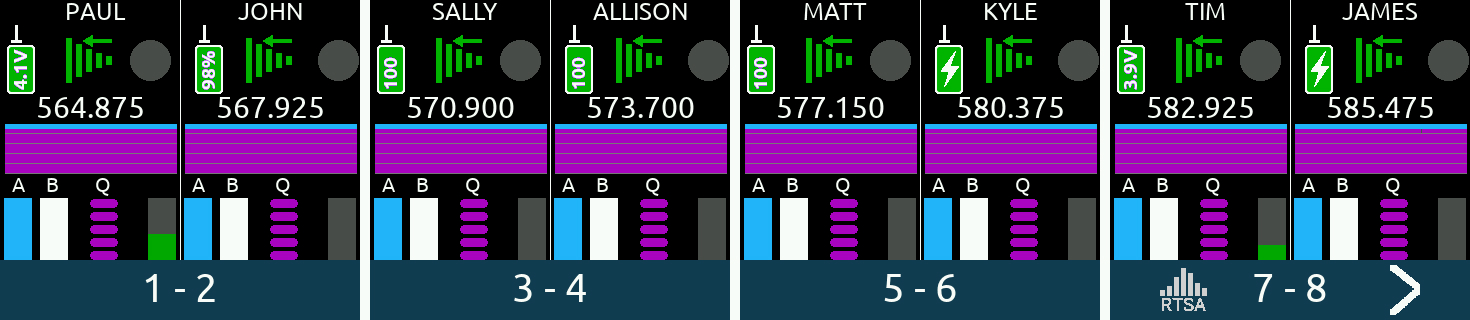
8RX View
(‘All’ View when no channel expansion licenses are installed)
4RX View
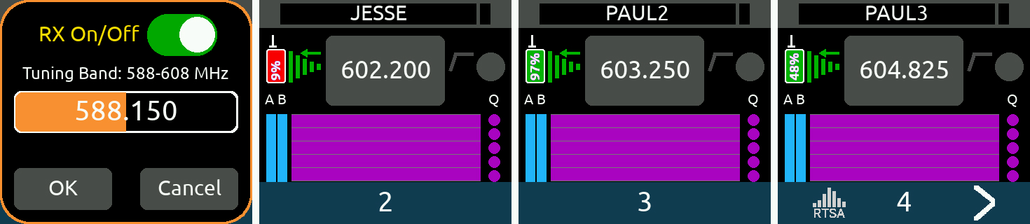
If NexLinked to an A20 transmitter, the frequency is automatically pushed to the transmitter unless System > More > NexLink Tuning Mode is set to Manual.
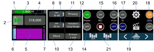
Displays a receiver channel’s received signal, audio level, control functions and status across the four screens.
Use the 1RX View to perform detailed control and monitoring of a receiver channel and its associated transmitter. The 1RX View has different control layouts depending on the following criteria:
Some 1RX View Layout examples
A20-Nexus | Mode | Description | 1RX View Layout |
Standalone | REC+RF | Channel sourced from a single A20 transmitter (See Example 1 below for a detailed description) | |
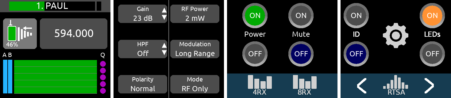
Standalone | RF Only | Channel sourced from a single A20 transmitter | |
Standalone | REC+RF | Channel sourced from multiple A20 transmitters (See Example 2 below for a detailed description) | |
Docked | RF Only | Channel sourced from a single A20 transmitter (expansion license installed) | |
Standalone | -- | Channel sourced from an A10-TX or non-NexLink’d transmitter | |
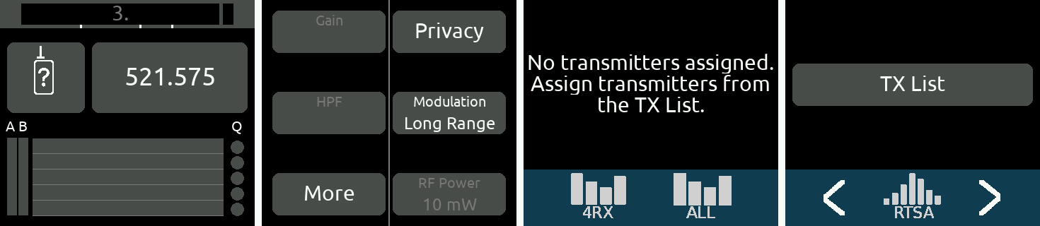
Standalone | -- | No transmitters are assigned to the channel. Tap the TX List button to assign a transmitter. |
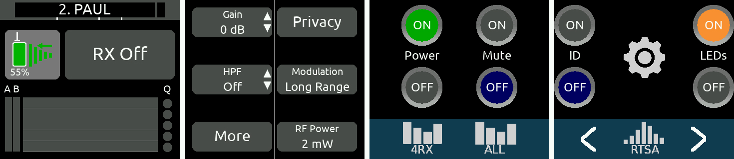
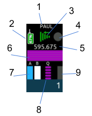
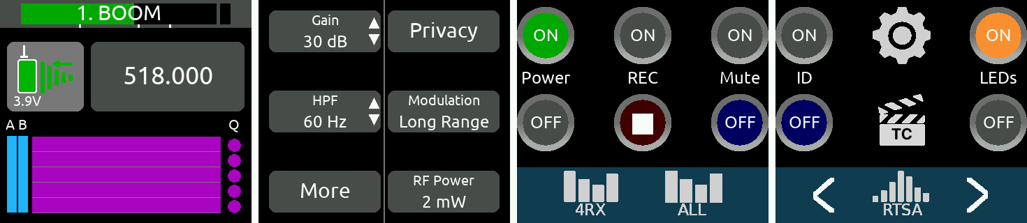
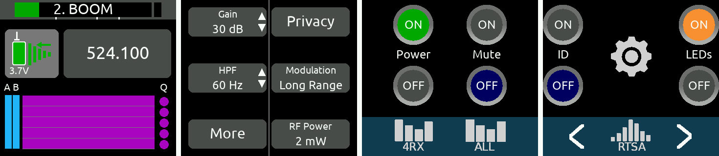
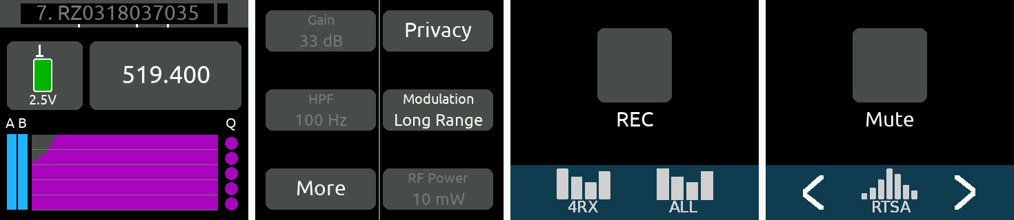
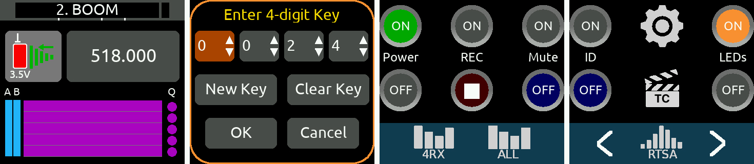
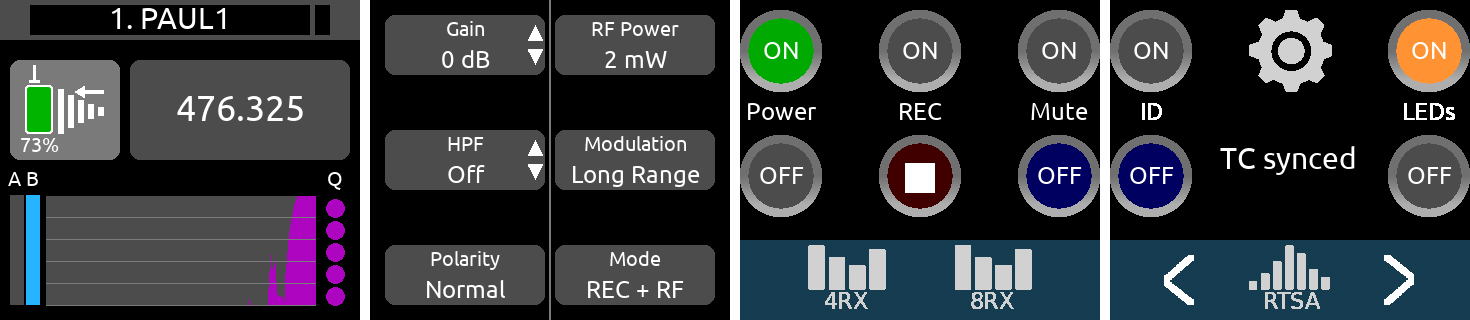
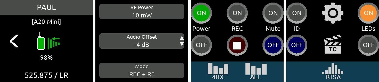
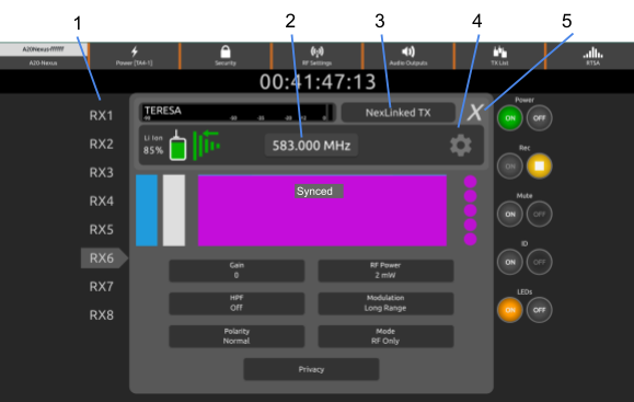
Example 1: 1RX View when sourced from a single A20-TX transmitter in REC+RF Mode, Standalone
For receiver channels that are sourced from a single transmitter, tap the NexLink RSSI meter to display the NexLinked Transmitter List from which you can select an A20 transmitter to NexLink to.
If NexLinked to an A20 transmitter, the frequency is automatically pushed to the transmitter unless System > More > NexLink Tuning Mode is set to Manual.
If NexLinked to an A20 transmitter, the modulation setting is automatically pushed to the transmitter unless System > More > NexLink Tuning Mode is set to Manual.
Note: A20 transmitters hold their synced timecode accurately for 4 hours after power down, then reset.
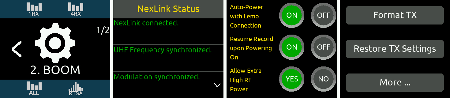
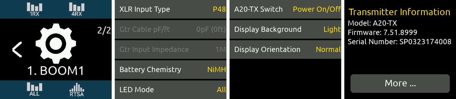
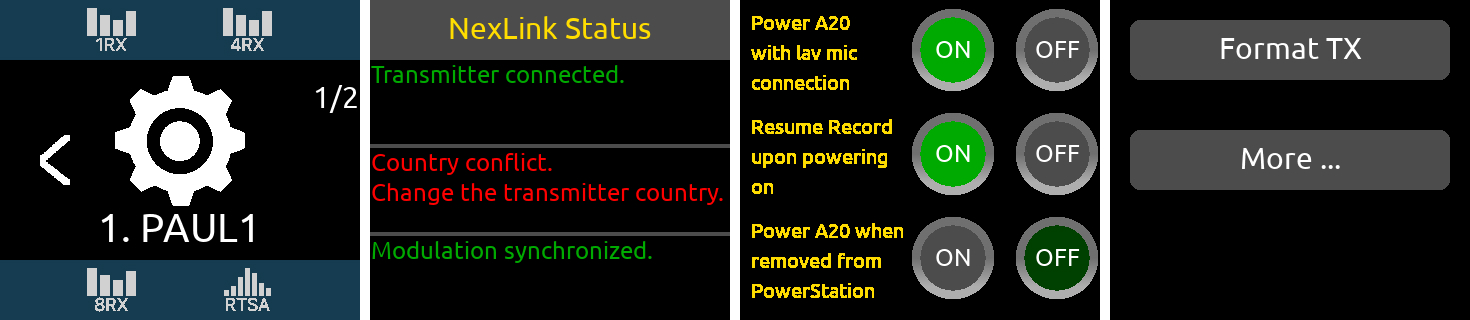
Gear Menu Page1/2
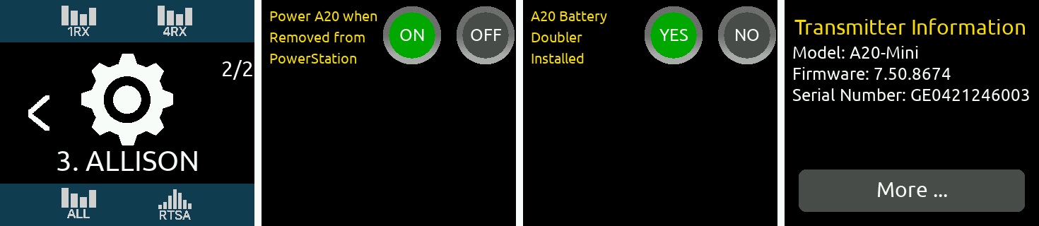
Page 2/2 for A20-Mini
Page 2/2 for A20-TX
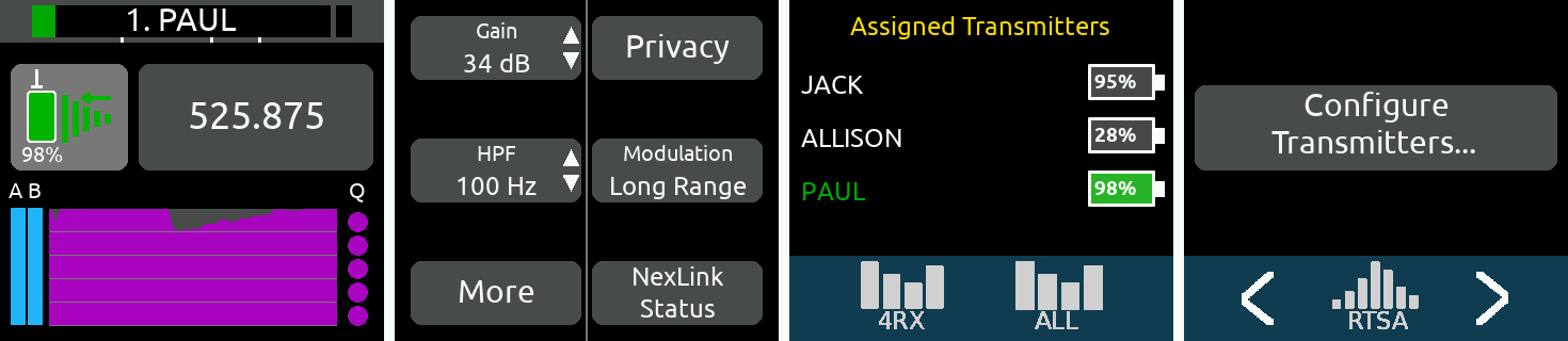
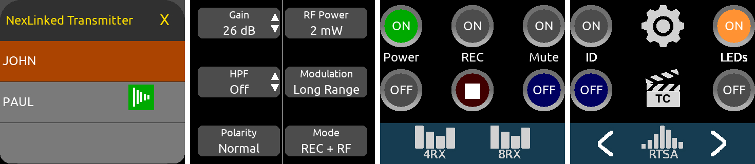
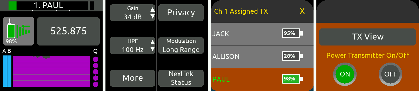
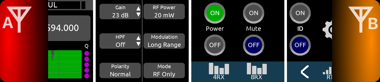
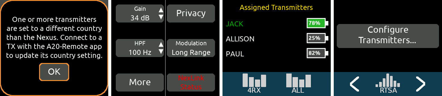
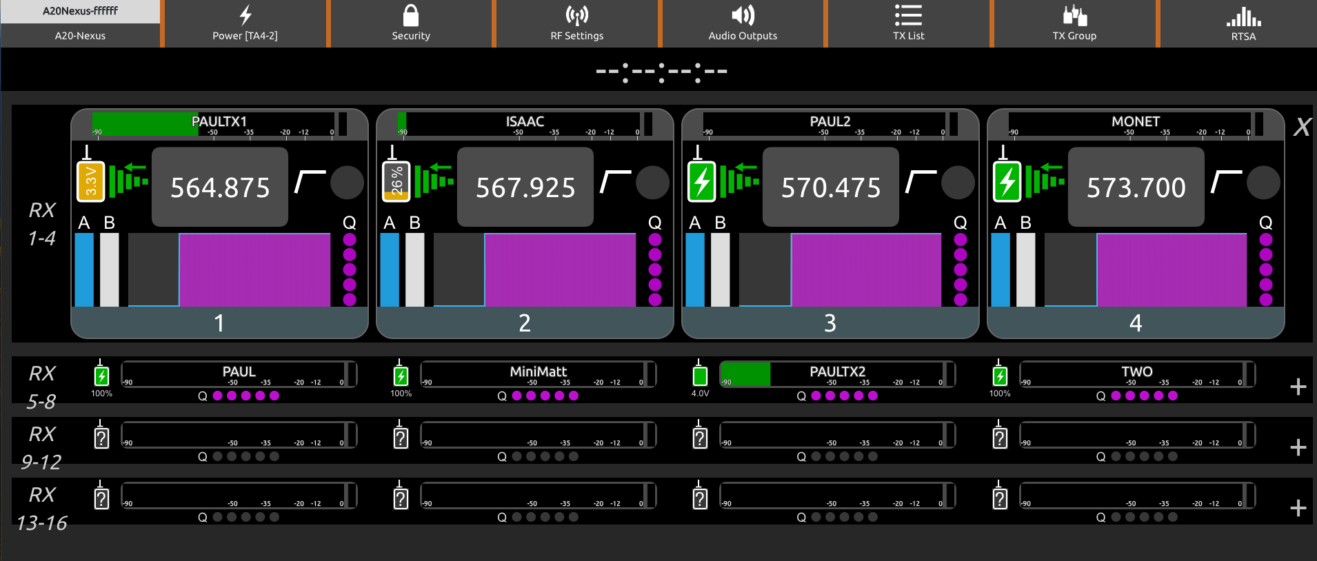
Example 2: 1RX View when sourced from multiple A20 transmitters in REC+RF Mode, Standalone
Many of the controls are the same as those described in Example 1. However, this 1RX View displays only those functions which are common to the receiver channel and all assigned transmitters. To change settings pertaining to only one of the assigned transmitters, tap 'Configure Transmitters…’ , highlight the transmitter, then tap TX View. The TX View can also be accessed from the TX List.
When a receiver channel is sourced from multiple transmitters, the Assigned Transmitters list in OLED 3 displays a list of all assigned transmitters. The transmitter name shown in OLED 1 and the one shown in green font in the Assigned Transmitters list, is the transmitter that is currently being received by the channel over the forward link.
Frequency, Modulation, and Privacy settings are applied to all assigned transmitters when NexLink Tuning Mode is set to Push.
Note: Make sure to have only one assigned transmitter powered up at a time otherwise they will interfere with one another. Power On/Off buttons are conveniently included in the view accessed by tapping ‘Configure Transmitters…’, to make it easy to ensure only one transmitter is powered on at a time: select a transmitter in the list then tap the power ON or OFF buttons as necessary.
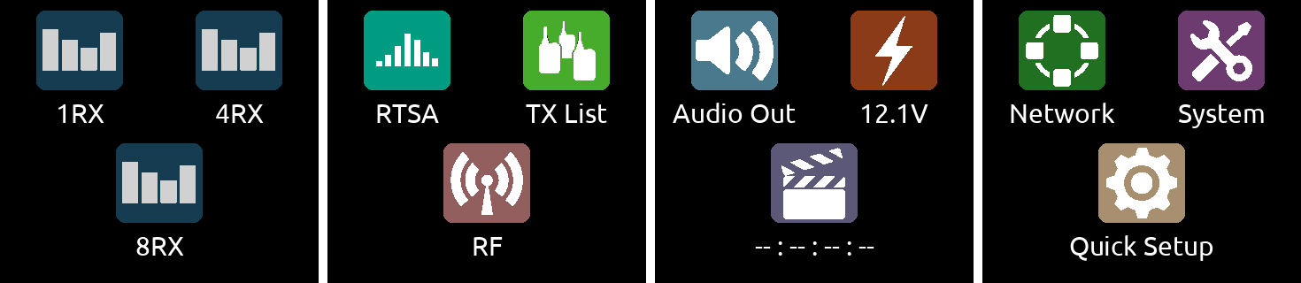
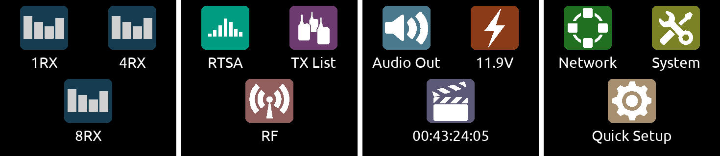
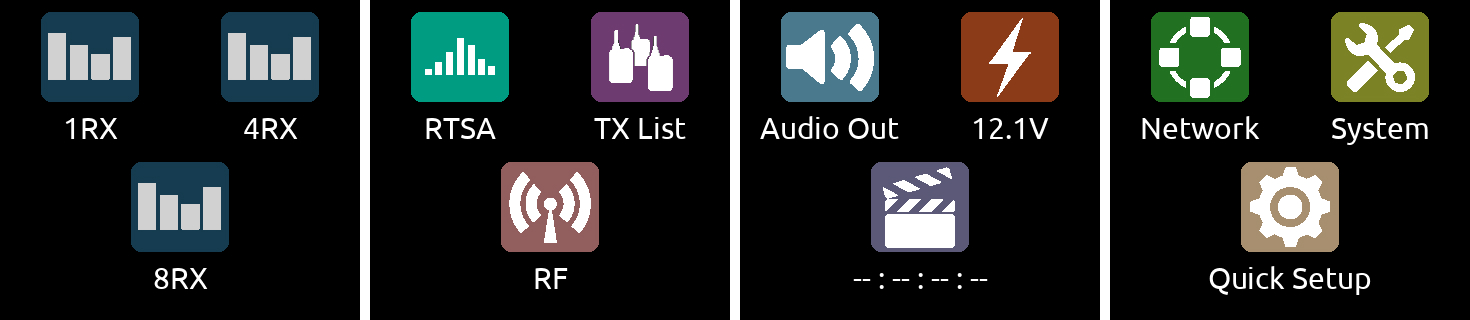
All the A20-Nexus settings are organized into menus which are accessed via the top level Main Menu.
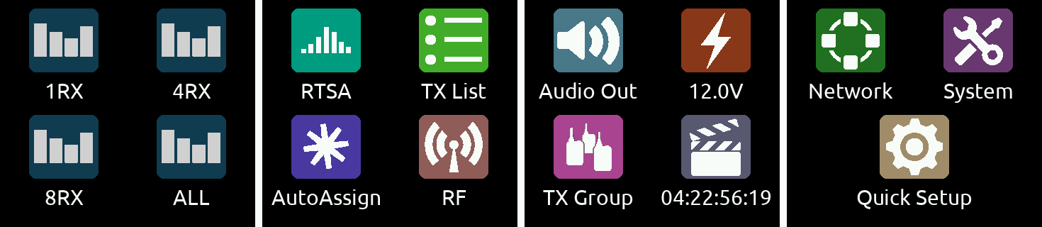
The triangle button cycles between the current RX view, Main Menu, and RTSA. Press the triangle button one or two times to display the Main Menu. The leftmost touch screen displays icons for the various RX views. Tap an RX View icon to jump to its RX View.
Main Menu
Menu | Description |
1RX | Displays a receiver channel’s received signal, audio level, control functions and status across the four screens. See Operating the A20-Nexus |
4RX | Displays 4 receiver channels, one per screen. See Operating the A20-Nexus |
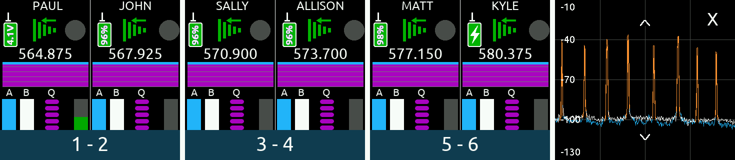
8RX | Displays 8 receiver channel strips, two per screen. See Operating the A20-Nexus |
ALL | Only available if expansion licenses are installed. Displays 12 or 16 channel strips depending on how many 4-ch expansion licenses are installed. |
RTSA | Displays the Real Time Spectrum Analyzer, a real time spectrum analysis tool for assisting in frequency coordination and selection of clean tuning bands and RF frequencies. |
TX List | Displays an inventory of paired transmitters and to which RX channels they are NexLinked. Pair/Unpair and view a transmitter’s settings. Power On/Off all NexLinked transmitters with one button press. |
AutoAssign | Tap to automatically scan the current tuning band for clean frequencies and assign them to active channels. The clean frequencies are automatically pushed to NexLinked transmitters. |
RF | Accesses antenna, tuning band, and RF History settings. |
Audio Out | Accesses D-Sub outputs, headphone output, sync reference, sample rate settings, and tone generator settings. |
Power | Displays the DC input voltage. Enables/disables DC Out 1 and 2 and configures whether the A20-Nexus should power on automatically when power is applied. |
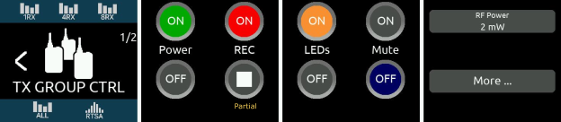
TX Group | Accesses the Transmitter Group Control menu where commands can be sent to all transmitters simultaneously. Commands include Power on/off, Record on/off, Mute on/off, LEDs on/off, RF Power, Modulation, Mode, Format, and ID. |
Timecode | Displays incoming LTC BNC timecode and frame rate |
Network | Network-related settings for Dante and Control |
System | 2 pages of various system settings: Page 1 includes screen, country, date/time, format USB drive, and firmware update functions. Page 2 includes operations pertaining to NexLink, Global TX Settings, installing plugins, Web App Password and more. |
Quick Setup | Load and Save Setup files for quick recall. Setups can be saved to 4 internal memory slots or to an external USB drive connected to the USB-A port. |
Tip: When in a menu, there are two ways to back out to the menu above.
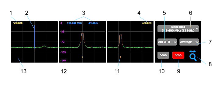
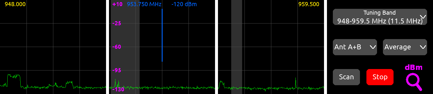
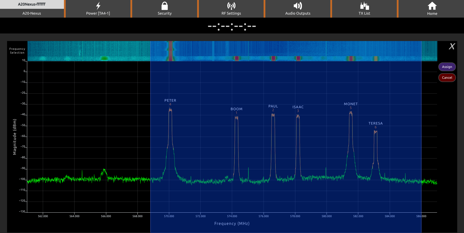
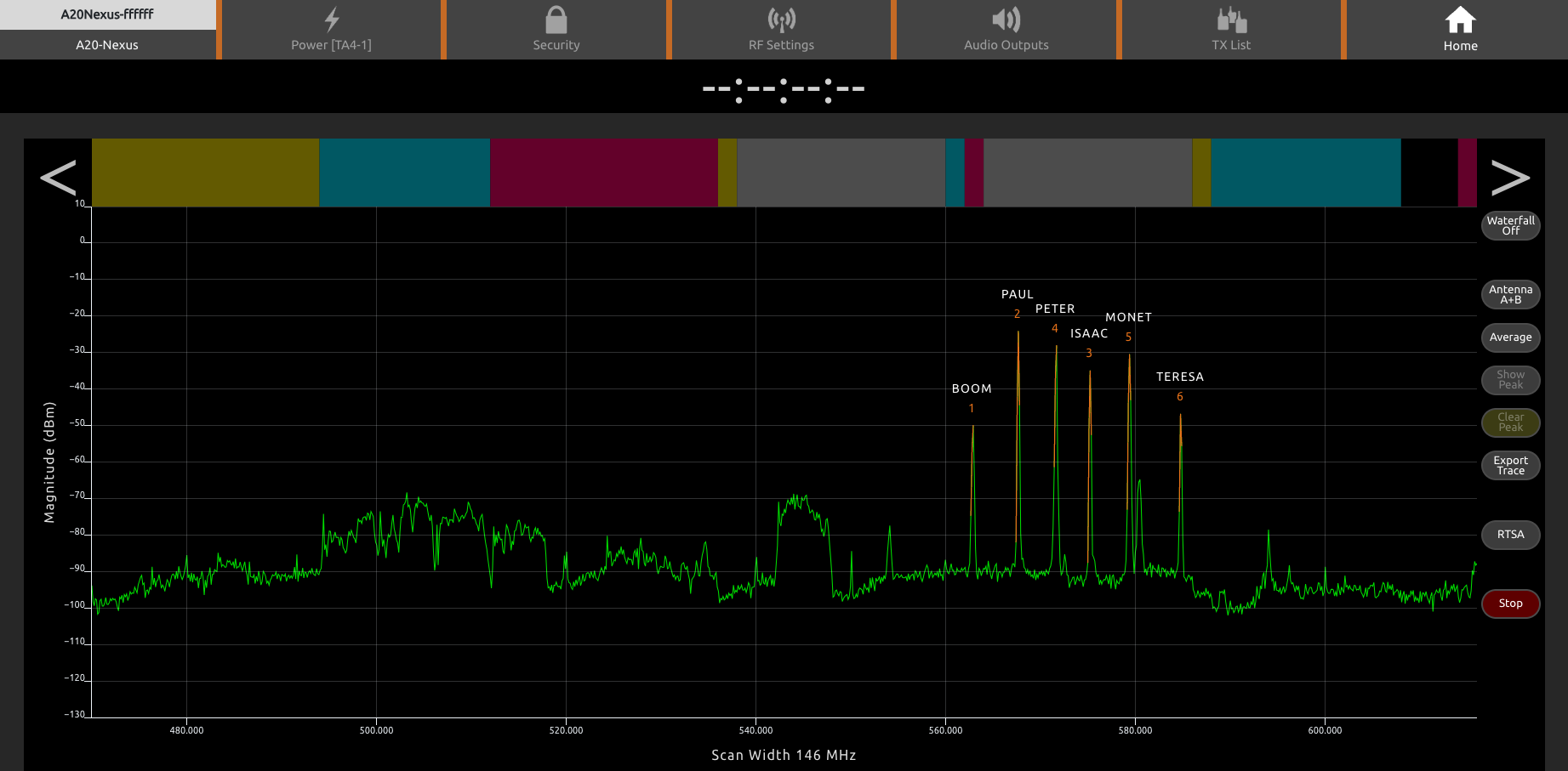
The RTSA is a real time, visual spectrum analysis tool for assisting in frequency coordination and selection of clean RF frequencies. The RTSA can operate over the entire SpectraBand range (169 MHz to 1525 MHz). The RTSA trace represents RF signal level (in dBm) on the vertical axis and RF frequency on the horizontal axis.
It has two modes of operation:
Typical Workflow
It is recommended to first use Scan mode to find the cleanest Tuning Band, then use RTSA mode to find the cleanest frequencies within that Tuning Band. Once clean frequencies are found they can be assigned to receiver channels and their associated NexLinked transmitters directly from the RTSA View.
The RTSA View can be displayed on a single screen (touch screen 4) or expanded across all 4 touch screens.
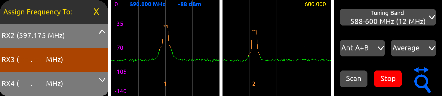
Single Screen RTSA View
Expanded RTSA View
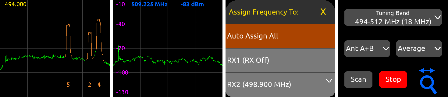
Press the Control knob to display the “Assign Frequency To:” list. Assign the blue frequency marker’s current frequency to any receiver channel or select ‘Auto Assign All’ to automatically scan and assign multiple clean frequencies at once. See AutoAssign for more information.
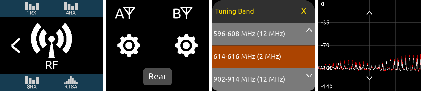
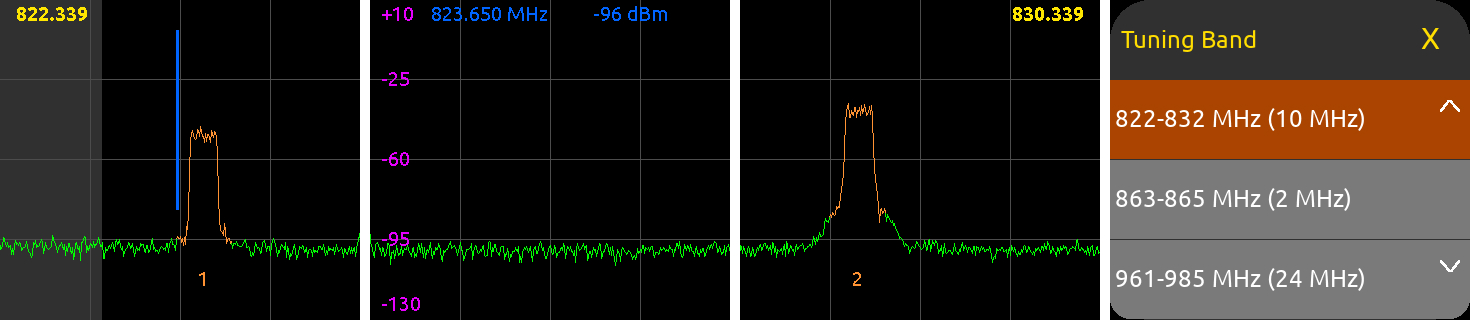
A Tuning Band is a tightly-filtered frequency band from within which Nexus’s receiver channels must operate. RF signals outside the selected tuning band are sharply attenuated to significantly reduce unwanted out-of-band RF interference. See Architectural Overview for further information
Tuning Band List
Quick Recall of a Tuning Band’s Assigned Frequencies
Each Tuning Band’s assigned receiver channel frequencies are stored and automatically recalled when selecting a Tuning Band. This is particularly useful for:
Note: Each Tuning Band’s assigned frequency cache is cleared when Nexus is powered down.
Tip: Use the Nexus Web App to export RTSA data as a .csv and .png file.
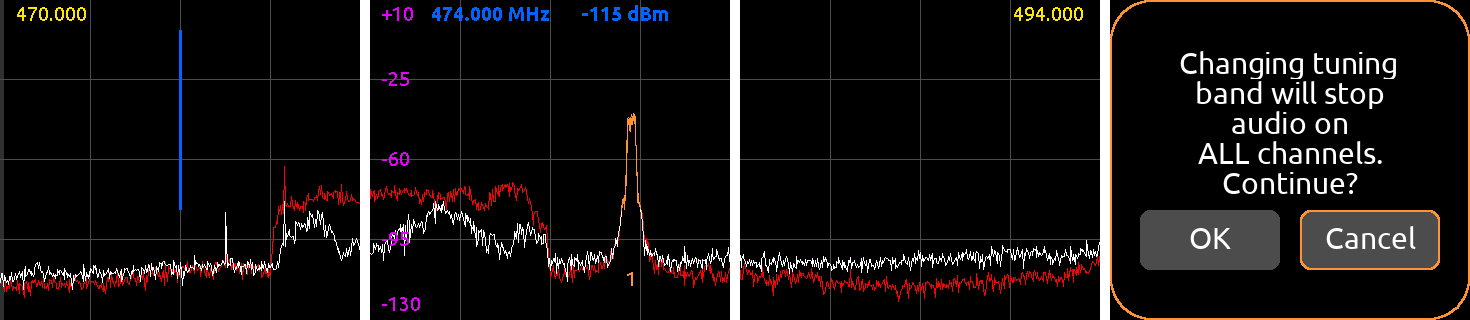
“Changing to Scan Mode will stop audio on ALL channels. Continue? [OK, Cancel]”
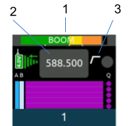
RTSA showing restricted frequency band
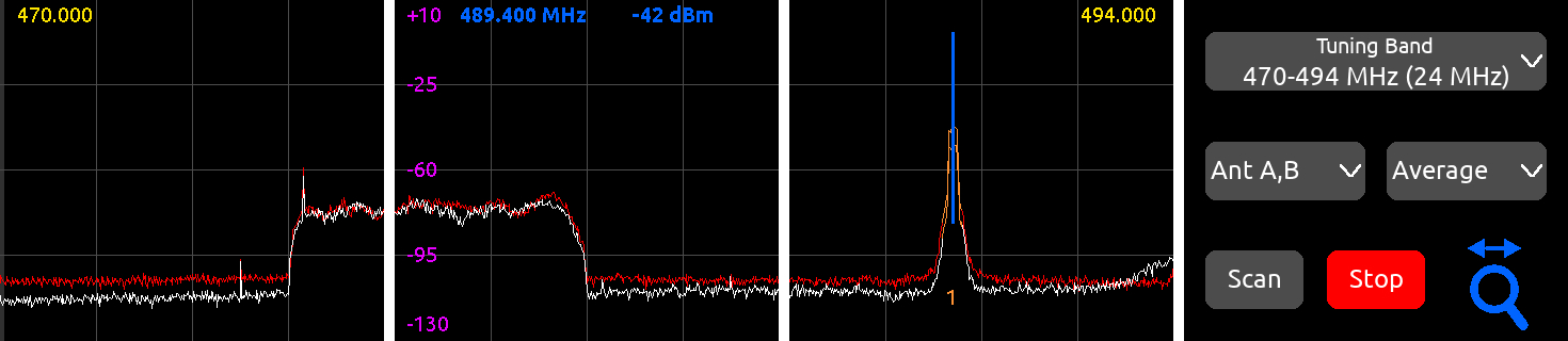
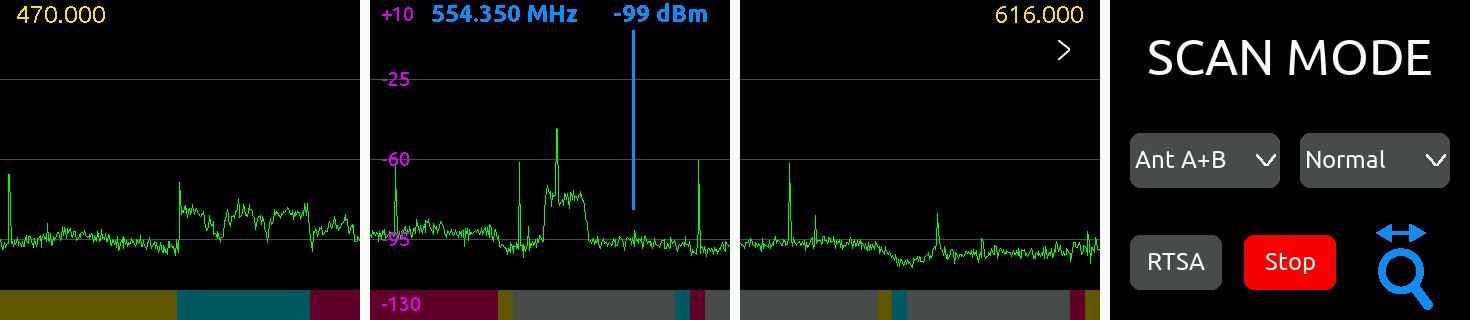
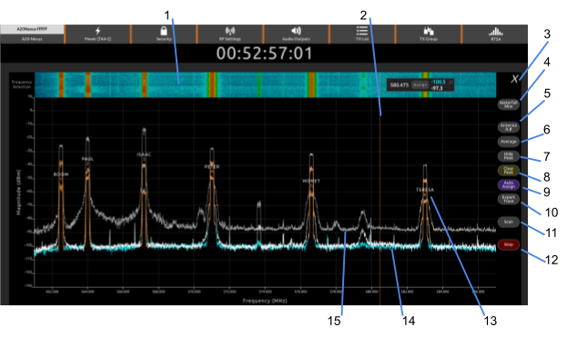
Use Scan mode to view the whole Nexus 169 MHz - 1525 MHz spectrum and zoom in to see smaller sections in more detail.
The complete scan trace is refreshed a few times a second. Scan mode makes it quick and easy to find and select a clean Tuning Band.
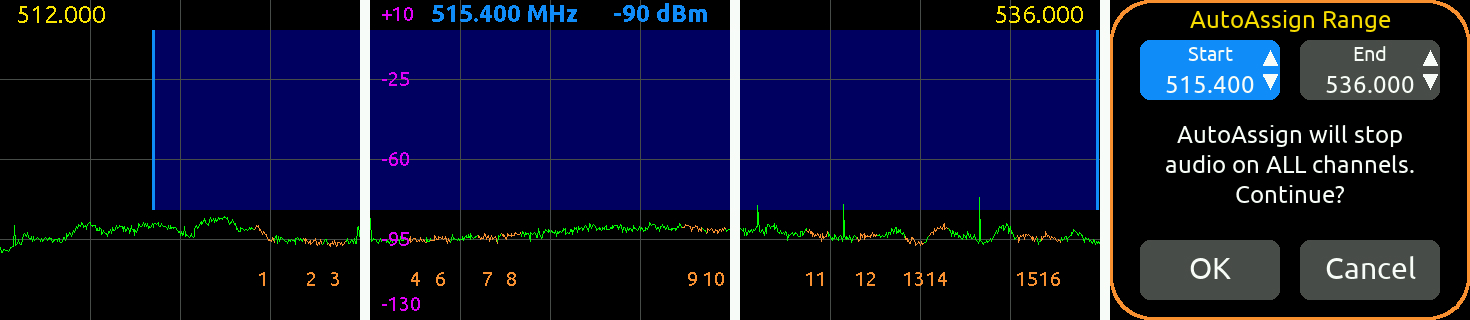
Tap the Main Menu > AutoAssign icon to analyze the whole or part of the current tuning band for multiple clean frequencies and automatically assign them to active* channels. If System > NexLink Tuning Mode is set to ‘Push to transmitter’, those frequencies are automatically assigned to NexLinked transmitters. *An active channel is 1) a NexLinked channel or 2) a non-NexLinked channel that has a frequency assigned.
Note: It is not possible to select a range less than 1 MHz.
Note: AutoAssign will stop audio on ALL channels.
After a number of seconds, a popup appears showing the number of frequencies that have been assigned to channels. If clean frequencies are not found for all the active channels, the popup asks whether to assign the remaining channels to less quiet frequencies. Select OK to continue. If clean frequencies are not found for those remaining active channels after the second attempt, a third and final attempt is offered.
AutoAssign can also be instigated from the RTSA View.
Note: Channels are not necessarily assigned in numerical order from lowest to highest frequency.
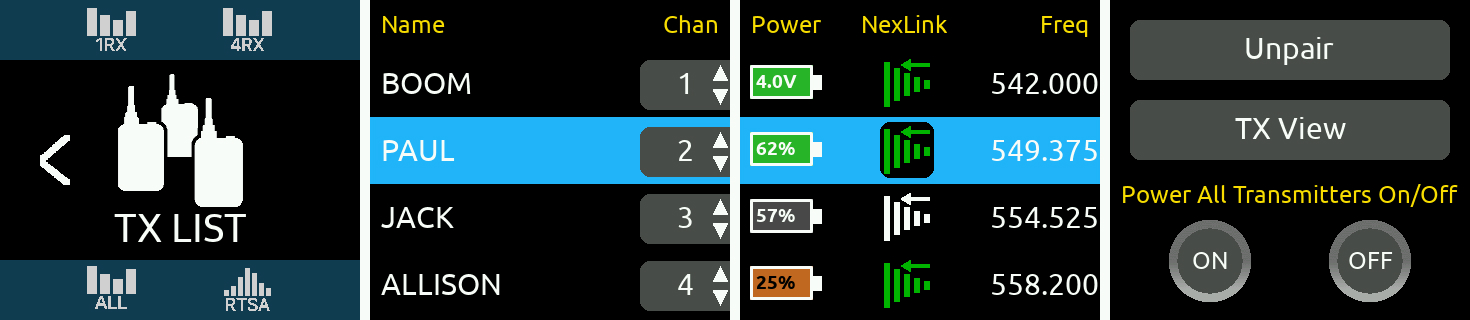
The A20-Nexus TX List is an inventory of all paired A20 transmitters and which RX channels, if any, they are assigned to. Up to 64 transmitters can be paired with the A20-Nexus. ‘Pairing’ is a process that establishes a NexLink wireless connection between the A20-Nexus and A20 transmitter. Once paired, an A20 transmitter can be controlled and monitored from its TX View and, if assigned to a receiver channel, from its associated 1RX View.
One or more A20 transmitters can be assigned to a receiver channel. When the A20-Nexus is set to ‘Push’ mode (see System>NexLink Tuning Mode), all transmitters assigned to a receiver channel are sent that channel’s RX Frequency, Modulation, and Privacy settings. This makes it easy to quickly switch between transmitters assigned to the same receiver channel, particularly useful in live scenarios such as switching to a backup transmitter or switching between a performer’s different mics or instruments that are being fed to the same channel on an external mixer.
NOTE: When multiple transmitters are assigned to the same receiver channel, ensure that only one of those transmitters is powered on, otherwise signals from these multiple transmitters will interfere with each other since they will all be operating on the same frequency.
Pairing an A20 Transmitter to the A20-Nexus
To establish NexLink wireless control between an A20 transmitter and the A20-Nexus, the transmitter must be added to the TX List in a process called ‘pairing’. Once paired, a transmitter can be assigned to a receiver channel. Paired transmitters that are not assigned to a receiver channel can still be controlled over NexLink via the TX View.
Pairing automatically assigns the transmitter to the next available receiver channel number. Should that transmitter not be required for a particular production or job, simply un-assign it by setting its channel number to ‘-’.
Once transmitters are paired, they remain permanently in the TX List until unpaired.
Tip: Use a USB Hub (or PowerStation-8M) to pair multiple A20 transmitters simultaneously by connecting it to the A20-Nexus’s USB-A port.
Unpairing Transmitters from the A20-Nexus
Rotate the Control knob to select a transmitter in the list, then tap the Unpair button in OLED 4. An ‘Are you sure …” popup appears. Tap OK to unpair and remove the transmitter from the TX List.
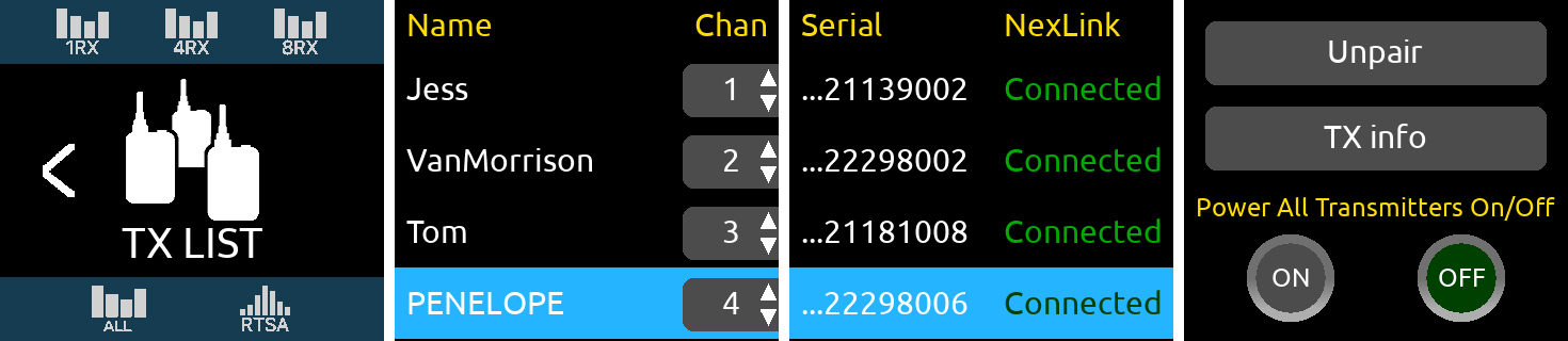
TX List Description
The TX List displays the following columns:
The TX List is sorted according to ascending receiver channel (Chan) number. When multiple transmitters are assigned to the same receiver channel, they are sorted in alphabetical order within that channel number’s group.
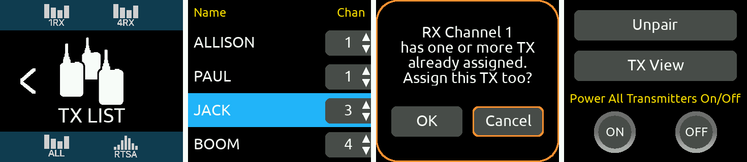
Assigning a Paired Transmitter to a Receiver Channel
Assigning a paired transmitter to a receiver channel enables synchronization of frequency, modulation, and privacy settings between the transmitter and that receiver channel. Up to 16 transmitters can be assigned to the same receiver channel.
Tip: Rotate the Control knob to scroll through the TX List. Select a transmitter by highlighting its row, then press the Control knob to jump directly to its receiver channel’s 1RX View.
Tip: The TX List icon in the Main Menu is yellow if not all transmitters are connected and green when all transmitters are successfully connected or when no transmitters have been paired. If using the A20-Remote app for control, it is best practice to fully close the A20-Remote app or disable transmitter control in the app’s Manage Transmitters view until transmitters are shown as connected in the TX List.
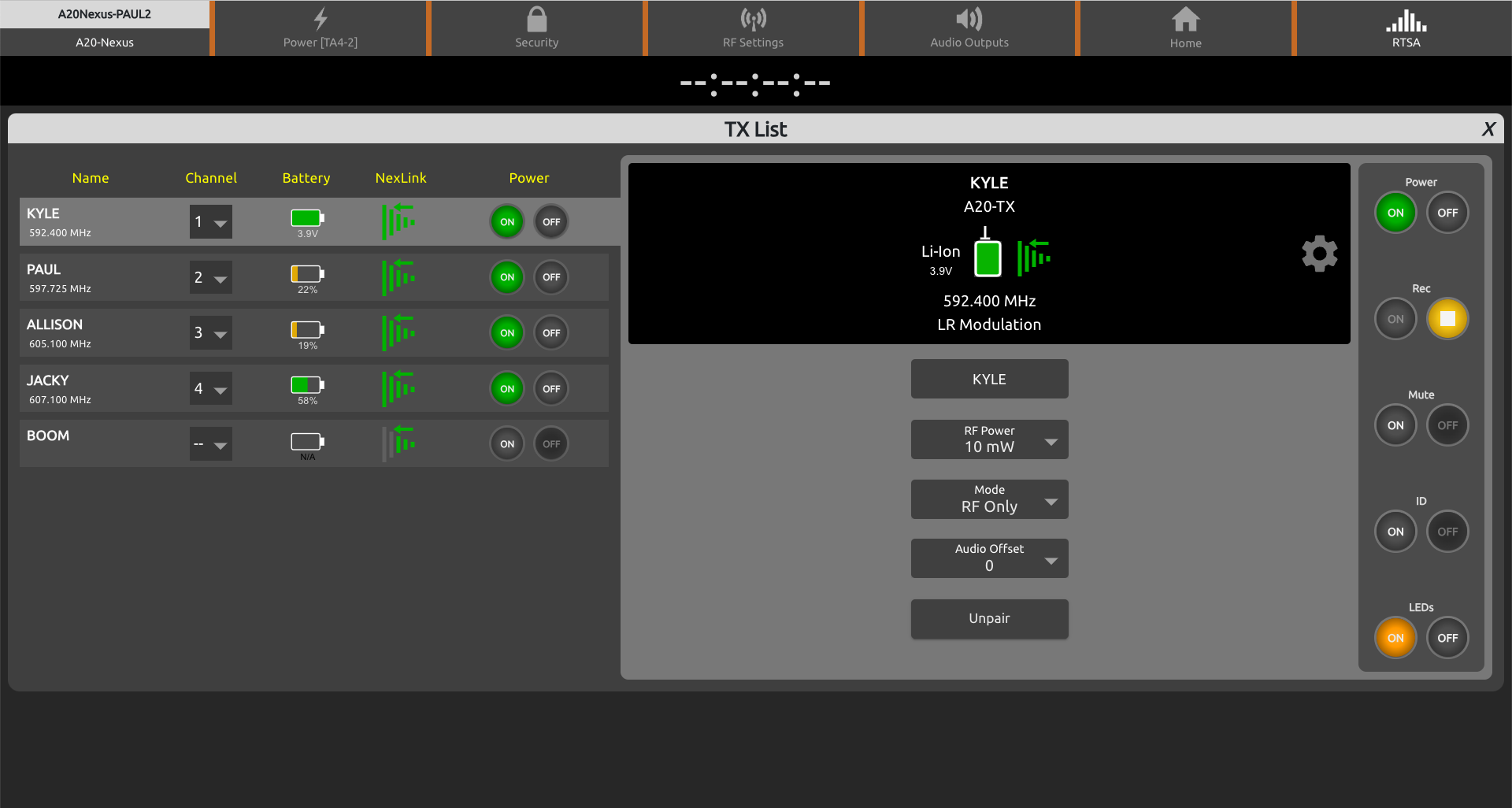
TX View
Tap the TX View button to access the selected transmitter’s settings. The button is grayed out when the transmitter is not connected via NexLink. TX settings can also be accessed via the 1RX View of the receiver channel that the transmitter is assigned to.
For a detailed description of many of the TX View’s controls which it shares in common with the 1RX View and its Gear menu, see 1RX View.
Power All Transmitters On/Off Buttons
Tap On to power on all NexLinked transmitters. Tap Off to power off all NexLinked transmitters. Other transmitter group commands are available in the TX Group menu. See TX Group.
Note: If multiple transmitters are assigned to a receiver channel, only the last transmitter being received over the forward link is powered on.
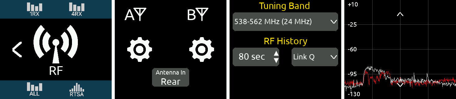
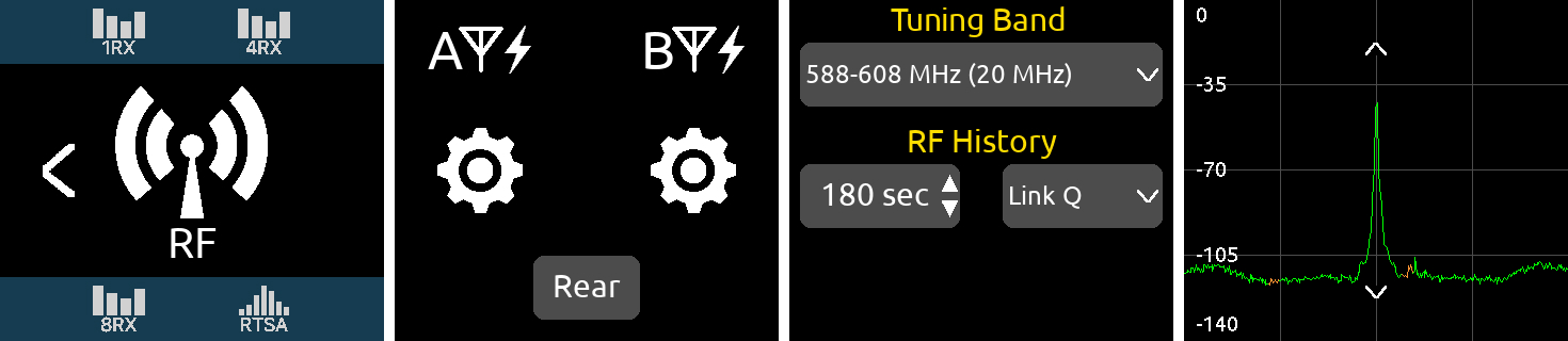
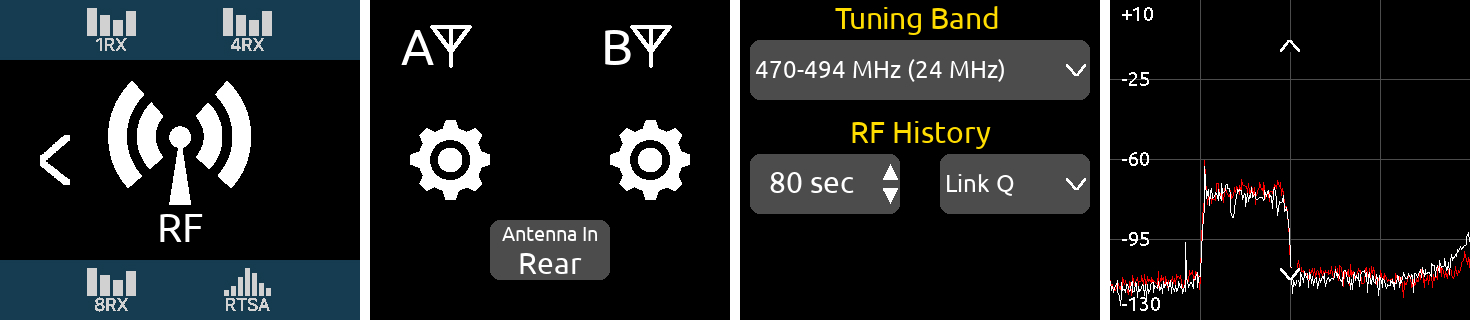
The RF Menu accesses antenna, tuning band, and RF History settings.
From the Main Menu, tap the RF icon to enter the RF Menu.
Antenna A/B Setup
The antenna inputs A and B can be switched as a pair between the front or rear panel BNCs. When set to front, the antenna’s matching rear BNC can be set to Cascade Out, ideal for daisy chaining units.
When daisy chaining A20-Nexus, it is recommended to use an external powered antenna to overcome the 3 dB splitting loss in the Nexus so that the receivers maintain excellent range.
See Antenna RF Overload Indication below.
The A20-Nexus indicates whether its A and B antenna inputs are approaching overload or overloading.
Tip: Things to try when an RF signal is approaching overload or overloading an antenna input:
When standalone, the A20-Nexus delivers its multichannel receiver audio via analog, AES, and Dante outputs. It can also be set up to convert incoming Dante audio and output it as analog or AES.
When docked to an 8-Series mixer/recorder, the Nexus’s multichannel receiver audio is output via the expansion port to the 8-Series and Nexus’s analog, AES, and Dante outputs are disabled.
Audio Outputs are configured in the Audio Out Menu.
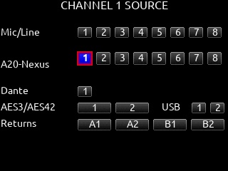
Routing A20-Nexus Receiver Audio when Docked to an 8-Series Mixer/Recorder
From an 8-Series channel screen, select any one of the A20-Nexus’s receiver outputs as channel source. A20-Nexus receiver outputs are only shown when an A20-Nexus is docked via the expansion port and enabled via the 8-Series System > Expansion Port menu.
888 Mixer/Recorder Channel Screen
Routing A20-Nexus Receiver Audio to Dante Outputs
The A20-Nexus receiver’s outputs [1-8] are hardwired to its Dante transmit channels [1-8] respectively.
Nexus’s Dante transmit channels are named A20Nexus_Tx1, A20Nexus_Tx2, A20Nexus_Tx3 etc.
Use Dante Controller running on a MAC or PC computer to route Nexus’s Dante outputs to any Dante device on the network.
See https://www.audinate.com/products/software/dante-controller
Note: A20-Nexus stores its Dante routing to/from other Dante devices, even after power cycling. As such, once setup, the computer running Dante Controller is no longer required unless the routing needs to be changed.
The A20-Nexus is identified on a Dante network by its ‘A20-Nexus Name’. The default A20-Nexus Name is A20-Nexus-[last 6 characters of the Nexus’s MAC address]. This name can be changed using Dante Controller or from the A20-Nexus’s Network menu.
Routing A20-Nexus Receiver Audio or Dante Inputs to Analog or AES Outputs
The A20-Nexus’s top and bottom D-Sub 25-pin connectors can be set to output receiver channel audio or incoming Dante audio as analog (line, -10, mic level) or AES signal. By default, the D-Sub outputs are set to output receiver channels.
Configure what to output from the top and bottom D-Sub connectors in the Audio Out > ‘Top D-Sub Output’ and ‘Bottom D-Sub Output’ lists. The options for both D-Subs are:
Note: RX 9-12 or RX 9-16 options are available to select if 4-channel expansion licenses have been installed.
Headphone Output
The A20-Nexus’s 3.5 mm stereo headphone output provides monitoring of the Nexus’s receiver channels or Dante inputs.
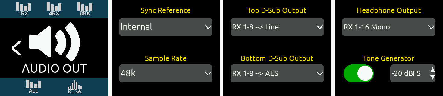
Audio Out Sample Rate
Audio Out Sync Reference
The A20-Nexus’s Dante and AES outputs can be sync’d to the following sync reference sources:
The following table indicates how the digital output sample rate is determined for each type of sync reference source:
Sync Reference | A20-Nexus Sample Rate Setting |
Internal | 44.1k, 48k or 96k |
BNC In (Word Clock) | Determined by incoming Word Clock frequency |
BNC In (LTC) | 44.1k, 48k or 96k |
Dante | Determined by Dante network sample rate |
8-Series (automatically selected when docked to 8-Series) | Determined by the 8-Series sample rate. Timecode and sync reference are received from the 8-Series. |
Tone Generator
Enable the Tone Generator to send tone at a specific level to all audio outputs. The tone level can be adjusted from -20 to 0 dBFS./
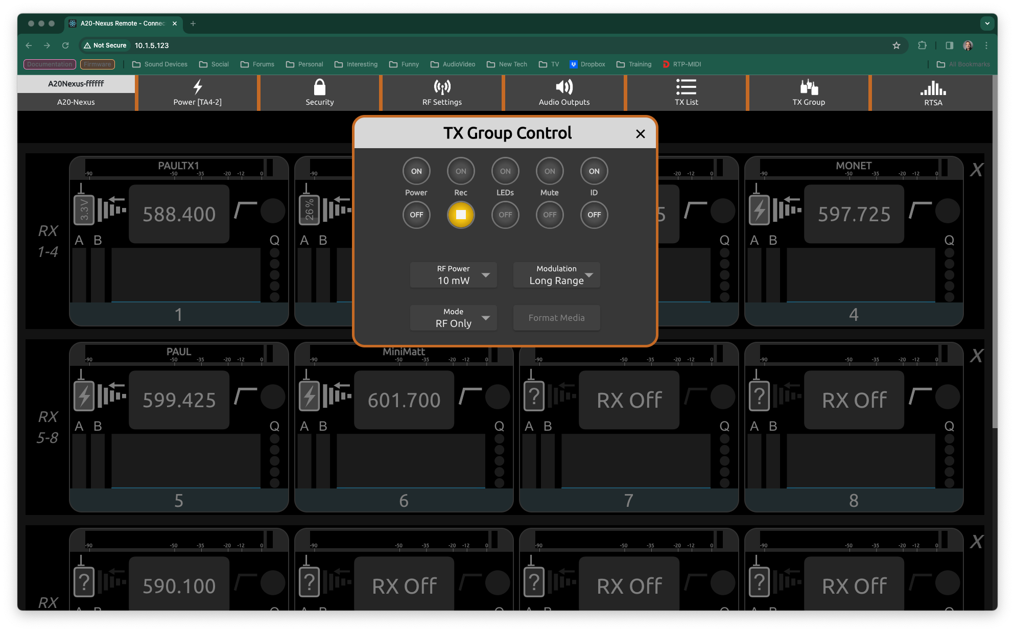
The TX Group menu provides access to commands that are applied simultaneously to all NexLinked transmitters that are mapped to RX channels. The following commands are supported:
If at least one transmitter does not respond correctly or match the command status, ‘Partial’ is displayed below the respective command’s buttons. Partial status for REC, LEDs and Mute functions are only reported for transmitters that are powered on.
Tap the More … button to cycle between the two pages of group commands. Page 2 includes Modulation, Mode, Format, and ID.
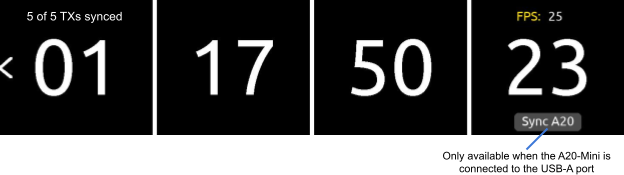
With NexLink, the A20-Nexus is able to simultaneously sync multiple A20 transmitters when they are set to REC only or REC+RF mode. This feature ensures zero-frame drift between multiple recording transmitters and therefore making it easy to sync with picture in post especially when the free SD-Utility software tool
(https://www.sounddevices.com/sd-utility-v2-00/) is used to conform and merge the individual A20 transmitter recordings into a single polyphonic wav file.
The Timecode menu displays incoming LTC and its frame rate. Tap the timecode slate icon in the Main Menu to access the Timecode menu. The incoming timecode is displayed below the icon making it unnecessary to enter the Timecode menu to check valid timecode is being received.
The A20-Nexus receives timecode in two possible ways:
Syncing A20 transmitters to A20-Nexus timecode.
The A20-Nexus supports both Dante and IP control. The built-in web server allows the A20-Nexus to be controlled via the Nexus Web App running on a web browser on any computer, tablet, or smartphone.
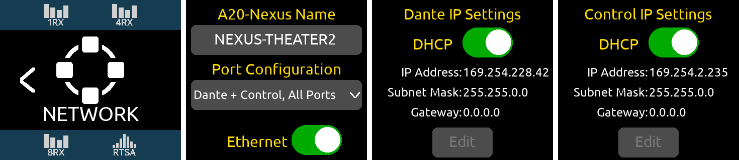
From the Main Menu, tap the Network icon to access the Network menu.
Port Configuration when A20-Nexus is Standalone
Incorporating a three-way network switch with two RJ45 ports and one SFP port, Dante and Control can be combined or segregated between the ports from the Network > Port Configuration list.
Port Configuration | Dante/Ctrl 1 (RJ45) | Dante/Ctrl 2 (RJ45) | Dante/Ctrl 3 (SFP) |
Control only, All Ports | Control | Control | Control |
Dante + Control, All Ports | Dante and Control | Dante and Control | Dante and Control |
Dante (1-2), Control (SFP) | Dante | Dante | Control |
Dante (1, SFP), Control (2) | Dante | Control | Dante |
Dante (SFP), Control (1-2) | Control | Control | Dante |
Tip: Disable Ethernet and Dante when not in use to reduce power consumption.
Port Configuration when A20-Nexus is docked to an 8-Series
Dante is disabled when the A20-Nexus is docked to an 8-Series and all ports are set to Control. Dante Settings and Port Configuration settings are hidden.
Note: When making network changes (Port Configuration, Ethernet On/Off, IP addresses, etc.), allow time for the changes to take place. This can take a minute or two.
A20-Nexus Name
Tap to enter a unique name for the A20-Nexus. The A20-Nexus Name is used as the Dante Device name in a Dante network and the network device name in a Control network.
The factory default A20-Nexus Name is A20-Nexus-[last 6 characters of the MAC address]
Ethernet On/Off
Enables/disables all ethernet ports. Disable Ethernet when not in use to reduce power consumption.
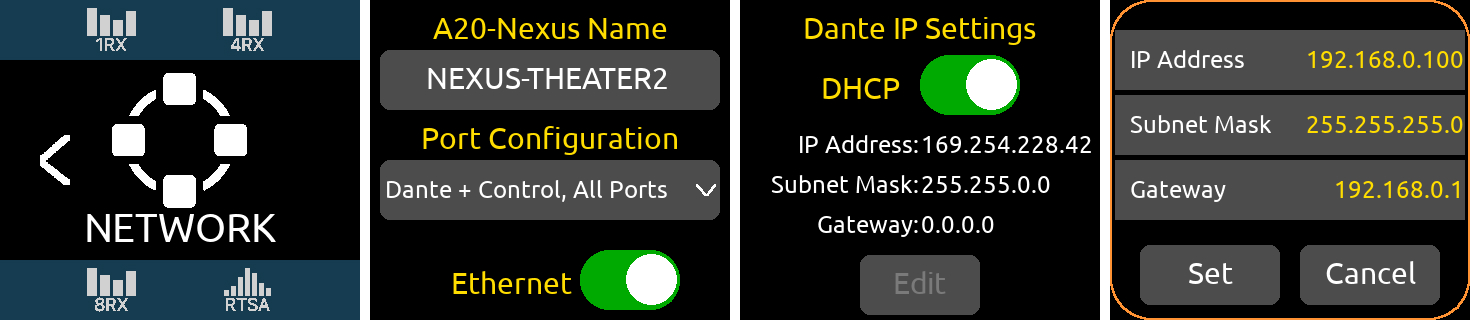
Dante and Control IP Settings
A20-Nexus supports both DHCP and static IP address setup. Dante and Control can be independently configured for DHCP or static IPs.
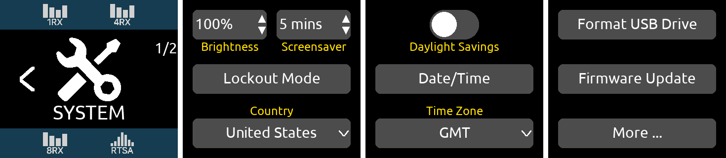
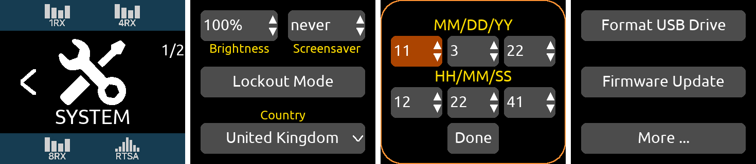
Tap the System Icon in the Main menu to access System settings. The System menu has two pages and includes various system settings organized over two pages. Switch between the pages by pressing the ‘More …’ button.
System Menu Page 1
Brightness
Tap to adjust the brightness of the OLED array and the LEDs.
Screensaver
The screensaver can help prevent OLED burn in. The screensaver time sets the duration from when the OLEDs were last touched to when the OLEDs display the screensaver. Select between 1 min, 5 mins, 15 mins, 30 mins, and never. The screensaver is canceled upon the touch of any front panel control.
Lockout Mode
Enable Lockout Mode to prevent unauthorized or accidental access to front panel controls including OLEDs, HP Encoder and triangle button. Lockout mode can be enabled locally or via the web app.
When Lockout mode is enabled, the HP encoder ring LED is backlit green to indicate that the A20-Nexus is still on.
To enable Lockout mode from the Nexus, tap the Lockout Mode button. The following popup is displayed:
“Are you sure?
To disable Lockout, tap the
left display whilst pressing HP.
OK, Cancel”
To disable Lockup Mode tap the left display whilst pressing the HP knob.
Note: You can also use Show Mode to prevent accidental changes to the front panel screens - this disables touch essentially making the screens read-only. Press and hold the Control knob for 3 seconds to toggle Show Mode on/off. When on, an orange border is displayed around each screen and if a screen is touched, a ‘The screen is locked’ popup appears.
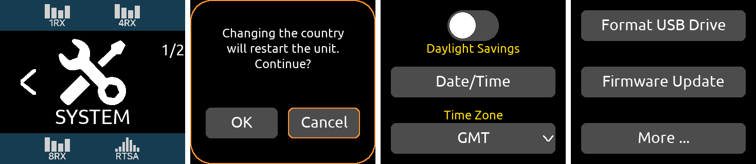
Country
The Country setting determines which Tuning Bands and RF frequencies are legally available for selection.
To set, tap the Country button then select the Country that you are in. Nexus displays the following prompt:
The Nexus will change the country and automatically restart when OK is selected.
Important
Date/Time
The A20-Nexus’s Date/Time has two purposes:
Tap Date/Time to bring up the Date/Time popup, then enter MM/DD/YY and HH/MM/SS. In each field, rotate the Control knob to set a value, then press the Control to jump to the next field. Tap Done to store.
Time Zone
Set the time zone from GMT -12:00 to GMT +13:00
Daylight Savings
Tap to toggle daylight savings on/off.
Format USB Drive
A USB drive connected to the USB-A port can be used for updating firmware and saving quick setup files. Before using the USB drive, it must be formatted by the A20-Nexus.
Firmware Update
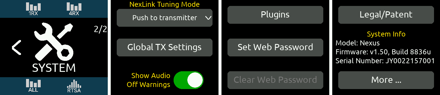
System Menu Page 2
NexLink Tuning Mode
Determines whether A20 transmitter frequency, modulation, and privacy settings are automatically sent (pushed) from the A20-Nexus to the A20 transmitter over NexLink.
Global TX Settings
The Global TX Settings menu provides options for enabling or disabling power off or stop confirmation popups.
Show Audio Off Warnings
When the toggle is off, the A20-Nexus does not show a warning popup that audio will stop when switching Tuning Bands and when switching to Scan mode.
Plugins
Tap Plugins to display and install licenses and plugins.
Set Web Password
Tap to set a security password for accessing the Web App.
Clear Web Password
Tap to clear the Web App password. The button is grayed out when no password is set.
System Info
Displays model name, firmware version, and serial number
More …
Tap to go to page 1 of the System menu.
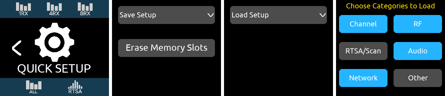
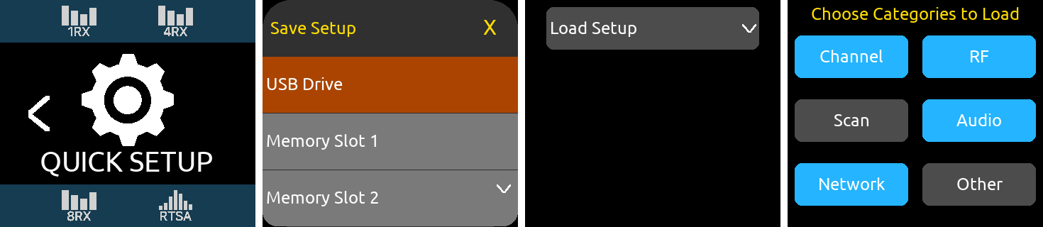
Quick Setup provides a way to save and load A20-Nexus settings. Settings are saved to internal memory slots 1-4 or to a USB thumb drive connected to the USB-A port.
Save Setup
Load Setup
Categories
Channel | RF Frequency |
| Modulation |
Privacy key | |
RX On/Off | |
Transmitters assigned to channel | |
| Polarity |
Gain | |
| HPF |
RF | Rear/Front Antenna Select |
| A and B Antenna Bias Power |
| A and B Antenna Cascade out |
| Current Tuning Band |
| RF History duration |
| RF History Type |
NexLink Tuning Mode (Push or Pull from Transmitter) | |
RTSA/Scan | RTSA/Scan Zoom Mode |
RTSA/Scan Vertical dBm Scale | |
RTSA/Scan Antenna Display Selection | |
RTSA/Scan Antenna Display Characteristics | |
Scan Width | |
Bandwidth | |
Audio | Top D-Sub Output Routing and Analog Output Level |
| Bottom D-Sub Output Routing and Analog Output Level |
| Headphone Out Routing |
| Headphone Out Gain |
Network | Port Configuration |
Ethernet On/Off | |
| Control: DHCP On/Off |
Dante: DFCP On/Off | |
| Control: Static IP address, subnet mask, gateway |
Dante: Static IP address, subnet mask, gateway | |
Other | Sync Reference |
| Sample Rate |
| Brightness |
| Screensaver |
| DC Out 1 |
| DC Out 2 |
| Turn On when Power is Applied |
Time Zone | |
Daylight Savings On/Off | |
TX List > Global TX Settings: Power Off confirmation, Stop Confirmation |
Default Settings
The Load Setup list also includes a ‘Default Settings’ option for restoring the A20-Nexus to default settings.
Remote control the A20-Nexus from anywhere in the world using the Nexus Web App, a browser-based remote control application for the A20-Nexus that can be run on any computer, tablet, or smartphone. It duplicates virtually all of the functions available from the A20-Nexus front panel. The integrated RTSA view is particularly useful for performing real time spectrum analysis over a wired or wireless network. Export the RTSA data as .csv and .png files to keep a record of a location’s RF environment. The .csv files can be imported into many of the popular frequency coordination applications.
The app’s GUI is dynamically optimized for the screen size on which it’s being viewed, whether a computer, tablet or smartphone screen.
Note 1: To ensure the web app functions correctly, use the latest version of your preferred browser. Chrome and Safari are recommended.
Note 2: When using a Wi-Fi access point with the A20-Nexus, it is best practice to switch the Wi-Fi access point to 5.8 GHz so that the Wi-Fi doesn’t interfere with the 2.4 GHz NexLink.
Accessing the Nexus Web App
Tip: When running multiple A20-Nexus receivers, open each one in its own separate browser tab.
For the purpose of this user guide, all web app screenshots are captured using an Apple MacBook Pro 15” computer.
Web App Main View
TX List
Web App 1RX View
Web App RTSA View
For the most part, the Web App’s RTSA duplicates the functionality of the A20-Nexus’s front panel RTSA. See RTSA.
Tip: With smartphones, tablets, and computers with track pad devices, pinch vertically to zoom in/out vertically, pinch horizontally to zoom in/out horizontally and pinch diagonally to zoom in/out horizontally and vertically. With a mouse, rotate the mouse wheel to zoom in/out and drag to move around the trace.
The Waterfall has three display options selected by the Waterfall button top right.
The Waterfall duration (Very Slow to Very Fast) and resolution (HIgh, Medium, Low) can be set in the RF Settings tab.
Tap or click the Assign button to display the Assign Frequency’ list. Assign the Frequency Marker’s displayed frequency to any receiver channel.
Periodically Sound Devices issues new firmware for the Nexus receiver. Make certain to register your product at the Sound Devices website to receive firmware update notifications.
Firmware is installed via a USB thumb drive inserted into the Nexus USB-A port. Download the latest firmware PRG from the Sound Devices website at https://www.sounddevices.com/download/
To update Nexus firmware
The A20-Nexus can be expanded from 8-channels to 12- or 16- channels by purchasing one or two 4-channel Expansion Licenses from the Sound Devices website. Permanent or rental licenses (1-week or 30-day) are available.
Channel Expansion licenses are installed via a USB thumb drive inserted into the Nexus USB-A port.
To install a license
Once installation has finished, the A20-Nexus will automatically restart.
Included
Optional
The A20-QuickDock enables the A20-Nexus to be docked to 833, 888, or Scorpio mixer-recorders. The bottom panel incorporates a multi-pin port that connects power from the 8-Series and passes the multichannel receiver digital audio from A20-Nexus to the 8-Series.
When docked on an 8-Series:
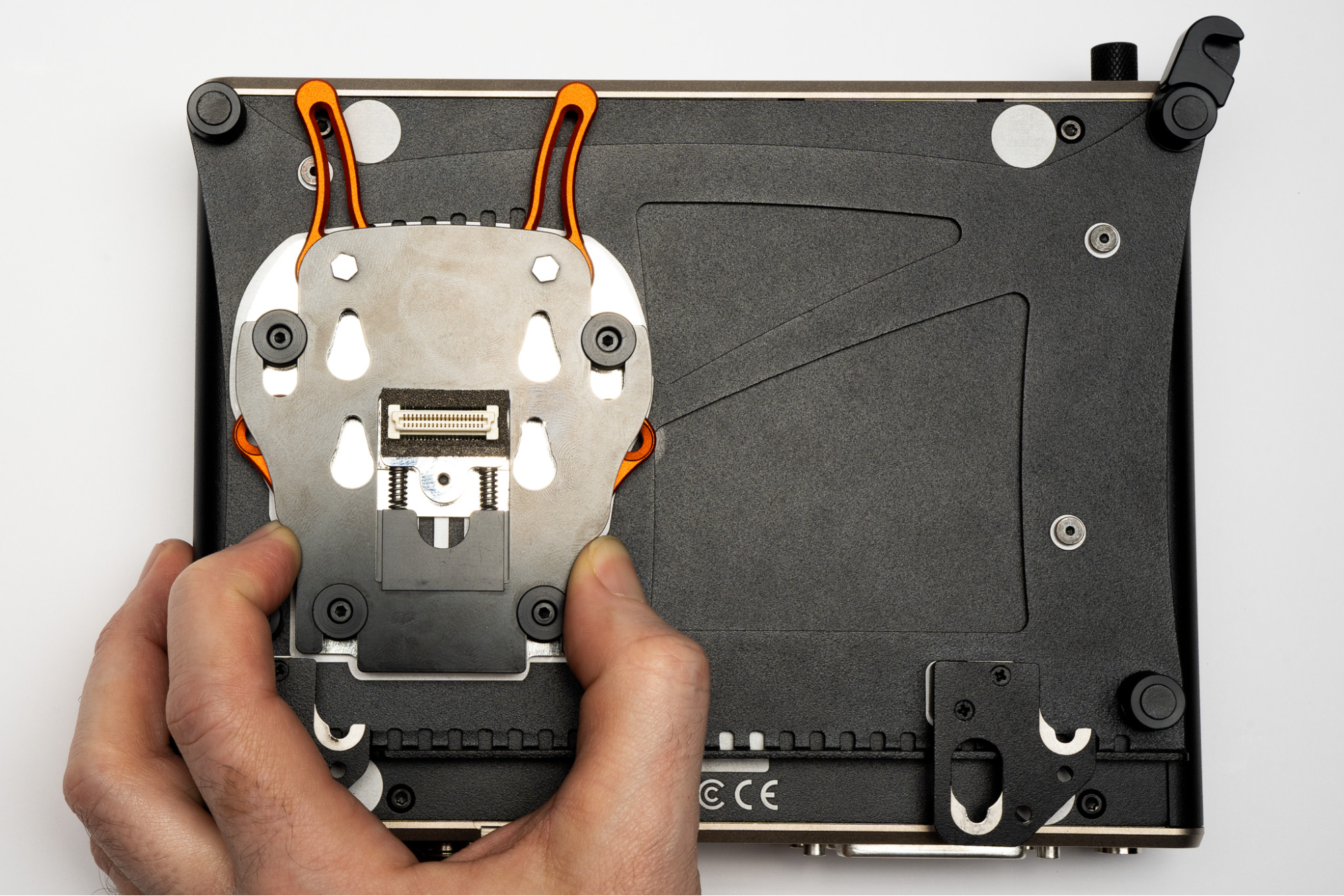
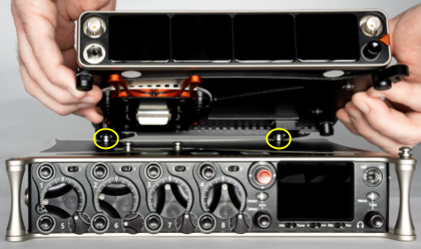
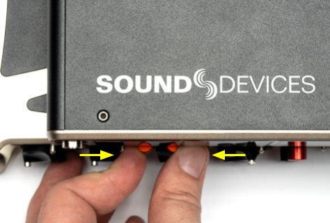
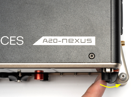
Attaching A20-Nexus to an 8-Series
The A20-QuickDock accessory is required to mount the A20-Nexus to an 8-Series mixer/recorder.
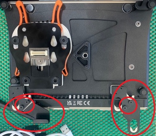
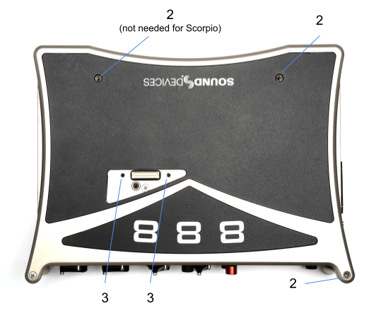
The A20-QuickDock comes with the following parts:
Use the following instructions for mounting and unmounting the A20-Nexus to an 8-Series mixer/recorder.
Scorpio Only Brackets
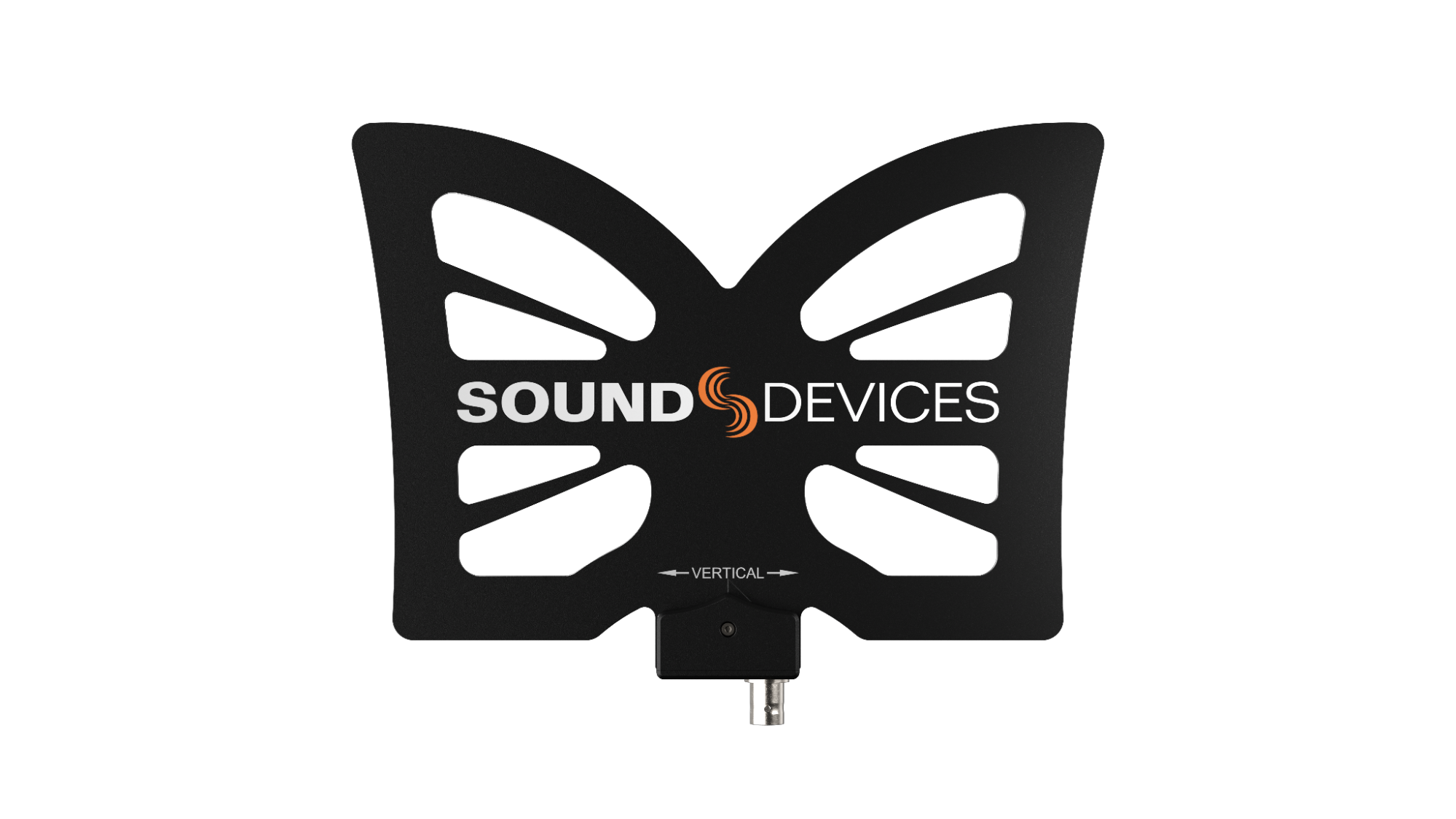
The A20-Nexus ships with two A20-Monarch, omnidirectional, wide-bandwidth (470-1525 MHz) antennas. These antennas provide uniform coverage and gain across the exceptionally wide SpectraBand tuning range of A20-Nexus. Each antenna is paired with a multi-function clamp and articulating arm, as well as an RG58 BNC-M to BNC-M cable (30 in.)
When purchased as a separate accessory, the A20-Monarch antenna also includes an RG174 BNC-M to SMA-M cable (18 in.)
The A20-Monarch kit comes with the following parts:
The A20-Shelf is a 1RU, 19” rack shelf designed to accommodate two A20-Nexus or one A20-Nexus and one PowerStation-8M side by side. The shelf’s rack ears have multiple fixing holes allowing the depth of the shelf to be adjusted. An A20-Nexus or PowerStation-8M can be mounted to the left, center, or right of the shelf. The A20-Shelf kit comes with the following parts:
Assembling the A20-Shelf
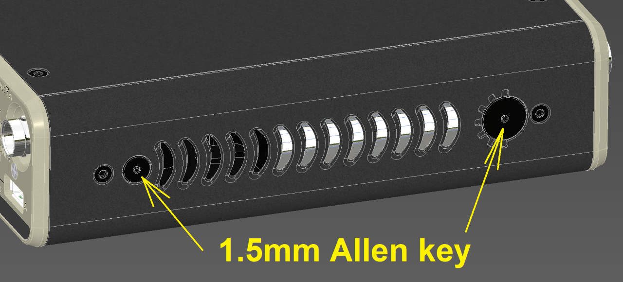
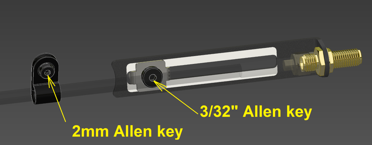
These easy-to-install adjustable antenna brackets are perfect for when the A20-Nexus is used in a bag and allow the 2.4 GHz antenna to be mounted on either side panel towards the front of the A20-Nexus, extending the 2.4GHz antenna out of the top of the bag for better NexLink range.
The A20-2.4G Ant+Mount Kit comes with the following parts:
Mounting the Antenna Brackets
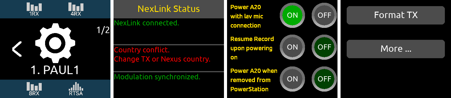
The NexLink Status View allows you to monitor NexLink communication between the A20-Nexus and A20 transmitters. This can assist in resolving NexLink issues. Access the NexLink Status View from the 1RX View Gear menu, TX View Gear menu, or, if the channel is sourced from multiple transmitters, directly from the 1RX View’s NexLink Status button.
A receiver channel’s Gear icon, NexLink Status button, and RF Frequency display turn red when there is a NexLink error.
NexLink Status Alerts
Message | Text Color | Description |
Searching for transmitter | Yellow | An A20 transmitter has been linked to the Nexus but NexLink communication to the transmitter has not yet been established or has been lost. The transmitter may be out of range, or its battery drained. |
Transmitter powered off | White | An A20 transmitter is NexLinked to Nexus and is powered off. |
NexLink connected | Green | An A20 transmitter has been successfully NexLinked to Nexus |
UHF frequency synchronized | Green | The frequency of the transmitter matches that of the receive channel that it is assigned to. |
Modulation synchronized | Green | The modulation of the transmitter matches that of the receive channel that it is assigned to. |
Frequency mismatch. Set the transmitter frequency. | Red | The frequency of an assigned transmitter does not match that of the receive channel. Manually set the transmitter frequency to the same frequency as the receiver channel or set the A20-Nexus’s NexLink Tuning Mode to ‘Push’. |
Modulation mismatch. Set the transmitter modulation. | Red | The modulation setting of an assigned transmitter does not match that of the receive channel. Manually set the transmitters modulation to the same modulation as the receiver channel or set the A20-Nexus’s NexLink Tuning Mode to ‘Push’. |
Privacy key mismatch. Set the transmitter privacy key. | Red | The privacy key setting of an assigned transmitter does not match that of the receive channel. Manually set the transmitters privacy key to the same modulation as the receiver channel or set the A20-Nexus’s NexLink Tuning Mode to ‘Push’. |
Country conflict. Change the transmitter country. | Red | The country code of the transmitter does match that of the Nexus. No synchronization of settings will be done until these match. Either change the country from A20-Remote or from the A20-Nexus. |
No receive frequency. Set the receive frequency | White | The frequency of the receive channel is set to 'Off’. In the 1RX or 4RX View frequency popup, set the channel to a valid frequency and ensure the channel is ‘On’. |
The wireless system operator needs to be aware of local regulations and comply with all applicable laws regarding operation of wireless devices.
In some restricted frequency bands, the operator will need to obtain an unlock code from Sound Devices to assign a restricted frequency to the transmitter. Once a license has been granted, please contact Sound Devices ([email protected]) to obtain the necessary unlock code.
An example of a frequency band requiring an unlock code in the United States is 1435-1525 MHz. Program Making and Special Events (PMSE) wireless operators typically call 1435-1525 MHz the "AFTRCC band". AFTRCC stands for Aerospace and Flight Test Radio Coordinating Council. This organization coordinates a number of frequency bands for use by air and spacecraft in the United States. This includes 1435-1525 MHz.
Per the United States Federal Communications Commission (FCC) rules, wireless microphones are allowed as secondary users in the 1435-1525 MHz AFTRCC band. This is detailed in the FCC Part 74 rules:
https://www.ecfr.gov/current/title-47/chapter-I/subchapter-C/part-74
One section of the Part 74 rules that's of particular interest to operators seeking an AFTRCC band license is 74.803(d):
https://www.ecfr.gov/current/title-47/chapter-I/subchapter-C/part-74#p-74.803(d)
Similar to the 914.5 - 944 MHz band, nationwide licenses are not typically granted for wireless operation in 1435-1525 MHz.
Generally speaking, a wireless operator needs to show they've used all other available spectrum before the AFTRCC will consider a license request in the 1435-1525 MHz range. If granted, the license is normally assigned for a specific location and a specific time range.
Sound Devices encourages all wireless operators to obtain a Part 74 license, and specifically to make sure applicable parts of the 600 MHz and 950 MHz range are included with their license application. This can help show an operator is aware of the available spectrum and is utilizing it responsibly.
More information on Part 74 licensing can be found here: https://www.local695.com/fcc-licensing/
Connector | Pin Assignments | Notes | |
DB-25 (Top and Bottom D-Sub) (Ch 1-8 Analog Out) | 1–Output 8 signal (+) 2–Output 8 Ground 3–Output 7 signal (-) 4–Output 6 signal (+) 5–Output 6 Ground 6–Output 5 signal (-) 7–Output 4 signal (+) 8–Output 4 Ground 9–Output 3 signal (-) 10–Output 2 signal (+) 11–Output 2 Ground 12–Output 1 signal (-) 13–unused 14–Output 8 signal (-) 15–Output 7 signal (+) 16–Output 7 Ground 17–Output 6 signal (-) 18–Output 5 signal (+) 19–Output 5 Ground 20–Output 4 signal (-) 21–Output 3 signal (+) 22–Output 3 Ground 23–Output 2 signal (-) 24–Output 1 signal (+) 25–Output 1 Ground | Mates with DB-25 Male Connectors Wired per the AES59 standard | |
DB-25 (Top and Bottom D-Sub) (Ch 1-8 AES Out) | 1–Digital Out 4 signal (+) 2–Digital Out 4 Ground 3–Digital Out 3 signal (-) 4–Digital Out 2 signal (+) 5–Digital Out 2 Ground 6–Digital Out 1 signal (-) 7–Unused 8–Unused 9–Unused 10–Unused 11–Unused 12–Unused 13–Unused 14–Digital Out 4 signal (-) 15–Digital Out 3 signal (+) 16–Digital Out 3 Ground 17–Digital Out 2 signal (-) 18–Digital Out 1 signal (+) 19–Digital Out 1 Ground 20–Unused 21–Unused 22–Unused 23–Unused 24–Unused 25–Unused | Mates with DB-25 Male Connectors Wired per the AES59 standard. Digital Out 1 = Ch 1,2 Digital Out 2 = Ch 3,4 Digital Out 3 = Ch 5,6 Digital Out 4 = Ch 7,8 | |
BNC (LTC/WCK) input | Center pin - signal Sleeve - ground | 75 ohm connector recommended | |
BNC (Front/Rear Antenna) | Center pin - signal Sleeve - ground | 50 ohm connector recommended | |
SMA (2.4 GHz, Rear NexLink) | Center pin - signal Sleeve - ground | 50 ohm connector recommended | |
SFP | Per SFF INF-8074i standard | For Dante and Control networks. | |
Ethernet (RJ45) | Standard 8P8C (female) | For Dante and Control networks. Dante/Ctrl 1 port supports PoE+ | |
TA4 (DC In 1 & 2) | Pin 1 = ground Pin 2 = Pin 3 = Pin 4 = positive volts | 10-18V | |
4-pin Hirose (DC Out 1 & 2) | Pin 1 = ground Pin 4 = positive volts | 10-18V, 500 mA max between both outputs (ie, 250 mA + 250 mA) | |
USB-A | Per USB-IF standard | 5V, 500mA | |
Specifications are subject to change without prior notice. For the latest information available on all Sound Devices products, visit our website: www.sounddevices.com
Patents: The A20-Nexus is protected by US patents US10678294B2, US20190166523A1, International patent WO2018022209A1, and several patents pending.
RF
Tuning
Modulation
Spurious Rejection
Cascade output
RF Bias output
Audio
Latency
Audio Frequency Response
Low Cut
Dynamic Range
Output Level
Audio Output Sample Rate
Digital Audio Output
Audio-Over-IP
Network
Dante Audio-Over-IP
Control
Connections
Powering
Sources
Levels
Environmental
Operating Temperature Range
Dimensions (H x W x D)
Weight
Frequency range
Gain
Pattern
Return Loss
Mounting Threads
Dimensions (H x W x D)
Weight
Sound Devices does not guarantee the absence of any interfering spurs across all bands in all situations. Some small spurs can originate within the Nexus, and others can come from many sources (Ethernet, AES/EBU interconnects, external mixer/recorders, USB drives, USB keyboards, etc.). This, combined with the extreme sensitivity of the Nexus's front end, mean that the user has to be very careful with the quality of cables used, as well as antenna and antenna cable routing and placement.
We highly recommend placing antennas as far as possible from other pieces of equipment, especially antennas from intentional transmitters such as IFB units.
Sound Devices recommends using high-quality, shielded Ethernet cables (whether using PoE+ or not) to minimize interference at RF frequencies caused by Ethernet. Additionally, it is a best practice to keep Ethernet cables as far away from the receiving antennas and the receiving antennas' coax cable (if used).
Do not attempt to service the A20-Nexus. The internal parts are microscopic and not user serviceable. Please send to Sound Devices for any service needs. https://service.sounddevices.com/contact-support/
Sound Devices, LLC warrants the items listed above against defects in materials and workmanship for a period of ONE (1) year from date of original retail purchase. Users who register their product directly with Sound Devices Technical Support using the online form or by phone, will receive an additional ONE (1) year of warranty coverage, extending the complete warranty period to TWO (2) years from the date of original retail purchase. In order to extend the warranty coverage period, registration must be completed within the initial ONE (1) year warranty period. Products must be purchased through authorized Sound Devices resellers to qualify for Warranty coverage. Damage resulting from the opening of a Sound Devices product or attempted repairs by a non-authorized Sound Devices repair technician will void warranty coverage.
This is a non-transferable warranty that extends only to the original purchaser. Sound Devices, LLC will repair or replace the product at its discretion at no charge. Warranty claims due to severe service conditions will be addressed on an individual basis.
THE WARRANTY AND REMEDIES SET FORTH ABOVE ARE EXCLUSIVE. SOUND DEVICES, LLC DISCLAIMS ALL OTHER WARRANTIES, EXPRESS OR IMPLIED, INCLUDING WARRANTIES OF MERCHANTABILITY AND FITNESS FOR A PARTICULAR PURPOSE. SOUND DEVICES, LLC IS NOT RESPONSIBLE FOR SPECIAL, INCIDENTAL, OR CONSEQUENTIAL DAMAGES ARISING FROM ANY BREACH OF WARRANTY OR UNDER ANY OTHER LEGAL THEORY. Because some jurisdictions do not permit the exclusion or limitations set forth above, they may not apply in all cases.
For all service, including warranty repair, please contact Sound Devices for an RMA (return merchandise authorization) before sending your unit in for repair. Products returned without an RMA number may experience delays in repair. When sending a unit for repair, please do not include accessories, including SSD drives, CF cards, batteries, power supplies, carry cases, cables, or adapters unless instructed by Sound Devices. Sound Devices repairs and replacements may be completed using refurbished, returned or used parts that have been factory certified as functionally equivalent to new parts.
Sound Devices, LLC
Services Repair RMA #XXXXX
E7556 State Road 23 and 33
Reedsburg, WI 53959 USA
Telephone: +1-608-524-0625
Product specifications and features are subject to change without prior notification. Read and fully understand this manual before operation.
Copyright© 2022 Sound Devices, LLC. All rights reserved. This product is subject to the terms and conditions of a software license agreement provided with the product, and may be used in accordance with the license agreement. This document is protected under copyright law. An authorized licensee of this product may reproduce this publication for the licensee’s own personal use. This document may not be reproduced or distributed, in whole or in part, for commercial purposes, such as selling copies or providing educational services or support. This document is supplied as a technical guide. Special care has been taken in preparing the information for publication; however, since product specifications are subject to change, this document might contain omissions and technical or typographical inaccuracies. Sound Devices, LLC does not accept responsibility for any losses due to the use of this guide.
LIMITATION ON SOUND DEVICES’ LIABILITY. TO THE FULLEST EXTENT PERMITTED BY LAW, SOUND DEVICES SHALL HAVE NO LIABILITY TO THE END USER OR ANY OTHER PERSON FOR COSTS, EXPENSES, DIRECT DAMAGES, INCIDENTAL DAMAGES, PUNITIVE DAMAGES, SPECIAL DAMAGES, CONSEQUENTIAL DAMAGES OR OTHER DAMAGES OF ANY KIND OR NATURE WHATSOEVER ARISING OUT OF OR RELATING TO THE PRODUCTS, THESE TERMS AND CONDITIONS OR THE PARTIES’ RELATIONSHIP, INCLUDING, WITHOUT LIMITATION, DAMAGES RESULTING FROM OR RELATED TO THE DELETION OR OTHER LOSS OF AUDIO RECORDINGS OR DATA, REDUCED OR DIMINISHED AUDIO QUALITY OR OTHER SIMILAR AUDIO DEFECTS ARISING FROM, RELATED TO OR OTHERWISE ATTRIBUTABLE TO THE PRODUCTS OR THE END USER’S USE OR OPERATION THEREOF, REGARDLESS OF WHETHER SUCH DAMAGES ARE CLAIMED UNDER CONTRACT, TORT OR ANY OTHER THEORY. “CONSEQUENTIAL DAMAGES” FOR WHICH SOUND DEVICES SHALL NOT BE LIABLE SHALL INCLUDE, WITHOUT LIMITATION, LOST PROFITS, PENALTIES, DELAY DAMAGES, LIQUIDATED DAMAGES AND OTHER DAMAGES AND LIABILITIES WHICH END USER SHALL BE OBLIGATED TO PAY OR WHICH END USER OR ANY OTHER PARTY MAY INCUR RELATED TO OR ARISING OUT OF ITS CONTRACTS WITH ITS CUSTOMERS OR OTHER THIRD PARTIES. NOTWITHSTANDING AND WITHOUT LIMITING THE FOREGOING, IN NO EVENT SHALL SOUND DEVICES BE LIABLE FOR ANY AMOUNT OF DAMAGES IN EXCESS OF AMOUNTS PAID BY THE END USER FOR THE PRODUCTS AS TO WHICH ANY LIABILITY HAS BEEN DETERMINED TO EXIST. SOUND DEVICES AND END USER EXPRESSLY AGREE THAT THE PRICE FOR THE PRODUCTS WAS DETERMINED IN CONSIDERATION OF THE LIMITATION ON LIABILITY AND DAMAGES SET FORTH HEREIN AND SUCH LIMITATION HAS BEEN SPECIFICALLY BARGAINED FOR AND CONSTITUTES AN AGREED ALLOCATION OF RISK WHICH SHALL SURVIVE THE DETERMINATION OF ANY COURT OF COMPETENT JURISDICTION THAT ANY REMEDY HEREIN FAILS OF ITS ESSENTIAL PURPOSE.
The “wave” logo is a registered trademark of Sound Devices, LLC. Windows is a registered trademark of Microsoft Corporation in the U.S. and other countries. Bluetooth LE is a registered trademark of Bluetooth SIG, Inc. Android is a registered trademark of Google. iPad, iPhone, and iOS are registered trademarks of Apple Inc. All other trademarks herein are the property of their respective owners.
FCC Conformity
NOTE: This equipment has been tested and found to comply with the limits for a Class B digital device, pursuant to part 15 of the FCC Rules. These limits are designed to provide reasonable protection against harmful interference in a residential installation. This equipment generates, uses and can radiate radio frequency energy and, if not installed and used in accordance with the instructions, may cause harmful interference to radio communications. However, there is no guarantee that interference will not occur in a particular installation. If this equipment does cause harmful interference to radio or television reception, which can be determined by turning the equipment off and on, the user is encouraged to try to correct the interference by one or more of the following measures:
—Reorient or relocate the receiving antenna.
—Increase the separation between the equipment and receiver.
—Connect the equipment into an outlet on a circuit different from that to which the receiver is connected.
—Consult the dealer or an experienced radio/TV technician for help.
This device complies with FCC RF exposure limits for general population / uncontrolled environments. A separation distance of at least 20 cm must be maintained between the antenna and all persons. This device must not be co-located with any other antenna or transmitter. This device has been approved to operate with the antenna type listed below:
Model: W1010 Type: Wireless External Antenna for 2.4 GHz Application
Manufacturer: PulseLarson Max. Gain: 2.0dBi
No change to the antenna type is permitted. Any change to the antenna could result in the device exceeding the RF exposure requirements and void the user’s authority to operate the device.
Changes or modifications not expressly approved by the manufacturer could void the user’s authority to operate the equipment.
To comply with FCC part 15 rules in the United States, the A20-Nexus receiver must be professionally installed.
It is the responsibility of the operator and professional installer to ensure that only certified antennas are to be used in the United States.
Industry Canada Conformity
This device complies with ISED RF exposure limits for general population / uncontrolled environments. A separation distance of at least 20 cm must be maintained between the antenna and all persons. This device must not be co-located with any other antenna or transmitter. This device has been approved to operate with the antenna type listed below:
Model: W1010 Type: Wireless External Antenna for 2.4 GHz Application
Manufacturer: PulseLarson Max. Gain: 2.0dBi
No change to the antenna type is permitted. Any change to the antenna could result in the device exceeding the RF exposure requirements and void the user’s authority to operate the device.
This Device complies with Industry Canada License-exempt RSS standard(s). Operation is subject to the following two conditions: 1) this device may not cause interference, and 2) this device must accept any interference, including interference that may cause undesired operation of the device.
Cet appareil se conforme aux normes ISED sur les limites d'exposition aux radiofréquences pour la population générale et environnements non controllés. Une distance minimale d'au moins 20cm doit être maintenue entre l'antenne et toute personne. Cet appareil ne doit pas être co-localisé avec toute autre antenne ou transmetteur. Cet appareil a été aprouvé pour fonctionner avec le type d'antenne ci-dessous:
Model: W1010 Type: Antenne externe sans fil pour application à 2.4 GHz
Manufacturer: PulseLarson Gain Max: 2.0 dBi
Aucun changement de type d'antenne n'est permis. Tout changement sur l'antenne pourrait causer l'appareil à excéder les limites d'exposition RF et annuler le droit de l'usager à faire fonctionner cet appareil.
Cet appareil est conforme avec Industrie Canada, exempts de licence standard RSS (s). Son fonctionnement est soumis aux deux conditions suivantes: 1) ce dispositif ne peut pas causer d’interférences, et 2) ce dispositif doit accepter toute interférence, y compris les interférences qui peuvent causer un mauvais fonctionnement de l’appareil.
WEEE Statement
If you wish to discard a Sound Devices product in Europe, contact Sound Devices (England) for further information.
Manufacturer’s Name: Sound Devices, LLC
Manufacturer’s Address: E7556 State Road 23 and 33 Reedsburg, WI 53959 USA
We, Sound Devices LLC, declare under our sole responsibility that the product
Product Name: A20-Nexus
Model Number: A20-Nexus
Description: Digital Wireless Receiver
is in conformity with the essential requirements of the following relevant Union harmonisation legislation:
Radio Equipment Directive (RED) 2014/53/EU
Low Voltage Directive 2014/35/EU
RoHS Directive 2011/65/EU
The following harmonised standards and/or normative documents were applied:
Health & Safety (Article 3.1(a) of RED) EN 62368-1:2014
EN 50566:2017
EMC (Article 3.1(b) of RED) EN 301-489-1 v2.2.3:2019
EN 301-489-9 v2.1.1:2019
EN 301-489-17 v3.2.4:2020
RF Spectrum (Article 3.2 of RED) EN 300 422-1 v2.1.2:2017
EN 300 328 v2.2.2:2019
EN 300 440 v2.1.1:2017
Signed for and on behalf of Sound Devices LLC:
Nov 21st, 2022
__________________________________ ______________________________________
Date Matt Anderson - Sound Devices, LLC President
Post Office Box 576
E7556 State Rd. 23 and 33
Reedsburg, Wisconsin 53959 USA
+1608.524.0625 main
800.505.0625 toll free (U.S. only)
www.sounddevices.com
A20-Nexus User Guide