A20-TX
Digital Wireless Transmitter
with GainForward, SpectraBand, and NexLink
User Guide v7.60
Table of Contents
NexLink Wireless Transmitter Control 4
Tuning the A20-TX and Receiver 17
File Transfer to a Computer 19
Installing the Optional A20-TX Switch 48
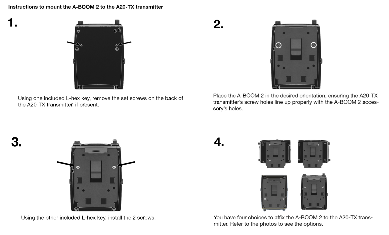
Installing the Optional A-BOOM 2 49
Sound Devices A20-TX bodypack transmitter is compatible with more input sources than any other transmitter, adding incredible flexibility to any audio kit. Whether worn on the belt of talent, mounted on a boom pole on a film set, or used in many other applications, the combination of audio quality, battery life, and RF performance is second to none. Additionally, worldwide travel is possible with the A20-TX transmitter, because it can easily be set to transmit on the legal frequencies of any country.
The A20-TX incorporates state-of-the-art features, such as NexLink remote control, Long Range modulation, GainForward, SpectraBand, internal 32-bit float recording, and more, to produce the best sound quality possible. The A20-TX is compatible with the A20-Nexus, A20-Nexus Go, A20-RX, and A10-RX digital receivers.
Key Features:
Our friendly and knowledgeable support team, based in the USA and the UK, is here for all your questions and comments. Our job is to make your job easier.
The A20-TX features SpectraBand, a technology that enables the A20-TX to tune over a super wide range of 169-1525 MHz.
Tuning within this range varies by country. For instance:
In the USA, the available frequency ranges are:
In the UK, the available frequency ranges are:
Please see https://www.sounddevices.com/available-frequencies/ for further detailed information on which frequency ranges are available for each country.
NexLink is a proprietary 2.4 GHz bidirectional wireless data link technology that allows multiple A20-TX transmitters to be controlled, monitored, and timecode synced from an A20-Nexus or A20-Nexus Go digital receiver over long distances. NexLink is designed to offer robust and reliable control over distances far exceeding that of the wireless audio transmission, even in the presence of Wi-Fi, Bluetooth, and other 2.4 GHz interference. The A20-Nexus and A20-Nexus Go can pair with up to 64 NexLinked transmitters at a time.
The A20-TX transmitter supports GainForward, a technology that eliminates the need to adjust audio gain at the wireless transmitter. Audio levels from the transmitter are controlled either directly at the mixer’s trim control or at the wireless receiver. If the source is too soft or too loud, adjust the transmitter’s audio level with a downstream mixer’s digital trim gain control. There is absolutely no noise penalty when the audio path remains 100% digital (i.e., A20 transmitter -> A20 receiver, A20 receiver digital audio output -> mixer digital audio input). Read more about GainForward at:
https://www.sounddevices.com/gainforward-explained/
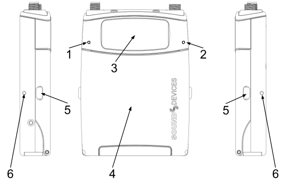
Front and Side Panels, Battery Door Closed
1: Power LED
Indicates power state. Can be turned off in the Settings>LEDs menu.
2: Audio Signal and Timecode LED
Audio/Timecode LED indicates audio activity and timecode status.
3: e-Paper Screen with Backlight
For display of settings and menus. The screen displays Name and Frequency when powered down even with batteries removed. The screen’s backlight comes on when the battery door is open to make it easy to navigate menus and change settings in the dark.
4: Battery Door
Lift to access the battery compartment, micro-SD card, power button, and navigation buttons. Closing the door returns to the Home screen.
5: Battery Door Release Catches
Squeeze to unlatch and open the battery door.
6: Belt Clip Mount Points
For attaching the A20-TX-CLIP belt clip. The belt clip can be attached either way, so the TX can be worn up or down.
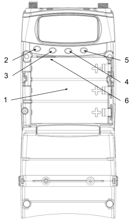
Front Panel, Battery Door Open
1: Battery Compartment
Accepts up to three AA batteries. Ensure batteries are inserted with the positive terminal facing to the right. Insert negative side first for easiest insertion. See Power
2: Power Button
This button is used to power the A20-TX on/off, or exit a menu.
3: Left Button
Press to navigate up or increase values.
When in the Home screen and in the RF or RF+REC modes, press the left button to jump straight to the RF Power menu.
When in the Home screen and in Rec Only mode, press the left button to jump straight to the Record menu.
4: Menu/Select Button
Press to access Menu (only accessible when the door is open). Press to select menu items and store values.
5: Right Button
Press to navigate down or decrease values.
While in the Home screen, press the right button to jump straight to the Battery Type menu.
6: Micro SD Card Slot
Insert a micro-SD for recording purposes.
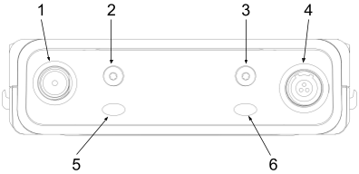
Top Panel
1: Antenna Connector
SMA connector. Attach an antenna with a length specific to the frequency in use. Using the wrong length of antenna reduces RF range. See Antenna Guide for more information.
2 & 3: A20-TX Switch Mounting Points
The optional user-programmable A20-TX Switch can be mounted here. The bayonet-style switch can be set to toggle RF on/off, mute, record, or power on/off.
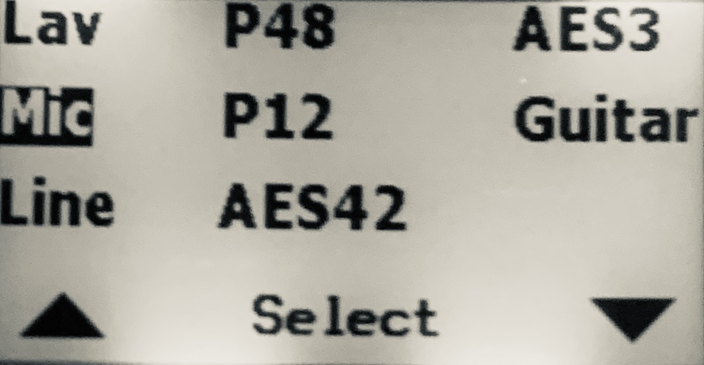
4: Multipurpose Audio Input
3-Pin Lemo connector for connecting 2- or 3-wire lavalier microphones, balanced mic (phantom or dynamic) or line inputs, AES42, AES3, or Guitar sources. Can be set to power the transmitter on/off when a lav mic is connected/disconnected.
5: Power LED
Indicates power state. Can be turned off in the Settings>LEDs menu
6: Status LED
Indicates various current states. Can be turned off in the Settings>LEDs menu
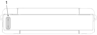
Bottom Panel
1: USB-C Port
Multifunction port used for:
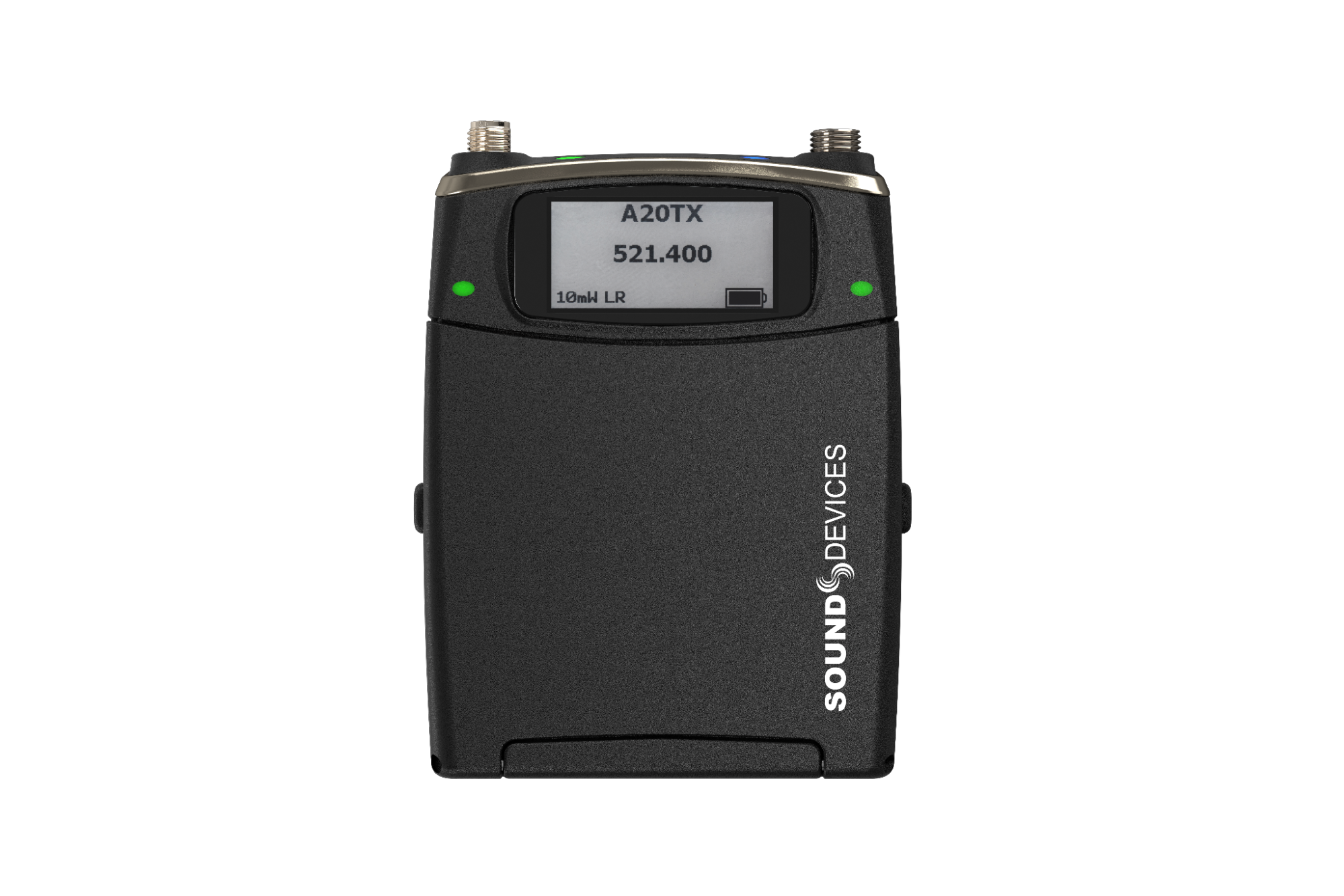
The home screen is the default screen when the A20-TX is powered up.
It is also automatically displayed whenever the A20-TX battery door is closed.
Important: When the A20-TX is powered on for the first time, the screen displays the following message: “To start, pair the A20-TX with the A20-Remote iOS or Android app”. Pairing enables full control of the A20-TX. Once paired, the message will not appear again. See A20-Remote for further details.
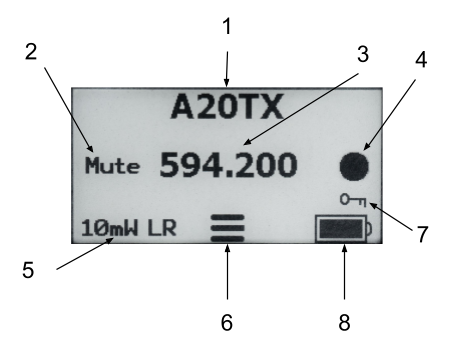
The Home Screen displays the following information:
1: Transmitter Name
Displays the transmitter name (max.12 alphanumeric characters), making it easy to identify the source feeding the transmitter (e.g. actor’s name, boom, etc.) The transmitter name is used as the volume name when formatting the micro-SD card and is also embedded in metadata as the Track Name of recorded WAV files. By default, the serial number of the A20-TX is assigned as the transmitter’s name. The name can be edited wirelessly using the A20-Nexus, A20-Nexus Go, or A20-Remote. The A20-TX name is also displayed on the A20-RX, A10-RX, and 8-Series when docked to an A20-Nexus, A20-Nexus Go, or SL-2.
The Home Screen’s transmitter name and frequency fields can be swapped. Select in the Settings>Display>Name menu.
2: Mute Status
Mute is displayed when the transmitter’s audio is muted.
3: Frequency / MHz
Displays the current transmission frequency.
4: Record Status
The record circle is displayed when the transmitter is recording.
5: RF Power and Modulation Type
Displays the current RF power and modulation type, LR (Long Range), Std (Standard).
When RF is enabled and the battery door is open, tap the left button to shortcut directly to the RF Power menu.
Displays ‘OFF’ when the RF Power Level is set to Off or when the optional A20-TX Switch (set to toggle RF on/off), is moved to the Off position.
6: Menu Icon
When the battery door is open, tap the middle button to access the Menu.
7: Privacy Status
The key icon is displayed when a privacy key is set.
8: Battery and Charging Status
Displays Battery Level.
Displays USB when powered from a USB power pack.
When charging, a lightning icon is displayed next to the Battery Status.
The A20-TX features a sophisticated powering system, allowing for powering from “1.5V” AA batteries, “3.7V Lithium” AA batteries, or from a USB portable power pack, giving the user maximum choice and flexibility in powering the A20-TX. Unlike other systems which require expensive custom battery packs, all of the batteries used by the A20-TX are very economical and can be purchased worldwide via Amazon or other outlets. The choice of eco-friendly rechargeable batteries or convenient, ubiquitous primary cells is totally up to the user. Additionally, the A20-TX features a built-in charger to recharge the Li-Ion and Li-FePO4 batteries via USB-C. Finally, when using the rechargeable “3.7V” batteries, it is up to the user to run with either one, two, or three batteries if the additional runtime is not needed.
The table below details operational characteristics for the different recommended AA battery chemistries:
Battery Chemistry | Recommended Model | Required No. of Batteries | Chargeable in the A20-TX |
NiMH | Eneloop or Eneloop Pro | 3 | No |
Alkaline | Energizer or Duracell | 3 | No |
Lithium Primary | Energizer Ultimate Lithium | 3 | No |
Li-Ion | Xtar 14500, 3.7V, 800mAh | 1, 2, or 3 | Yes |
LiFePO4 | Shockli 3.2V, 650mAh | 1, 2, or 3 | Yes |
Notes:
About the different battery chemistries:
Opening/Closing the Battery Door
When the door is closed, the display automatically switches to the Home screen. Open the battery door by squeezing the side panel release catches and lifting. When the door is opened, the display backlight turns on.
Powering On for the First Time
When the A20-TX is powered on for the first time, the screen displays the following message: “To start, pair the A20-TX with the A20-Remote iOS or Android app”. Pairing enables full control of the A20-TX. Once paired, the message will not appear again. See A20-Remote for further details.
Powering from AA
To power the A20-TX using AA batteries:
Note: When inserting batteries, the A20-TX will remain powered off (or automatically power up) depending on what the power state was when the A20-TX was previously shut down.
Charging from USB-C
Only Li-Ion and LiFePO4 batteries can be charged in the A20-TX. To charge Li-Ion or LiFePO4 batteries from USB-C:
Auto Power with Lemo Connection
When the ‘Auto power with Lemo connection’ feature is enabled in A20-Remote, A20-Nexus, or A20-Nexus Go, connecting a source to the Lemo connector automatically powers on the transmitter. Disconnecting the Lemo automatically powers the A20-TX off.
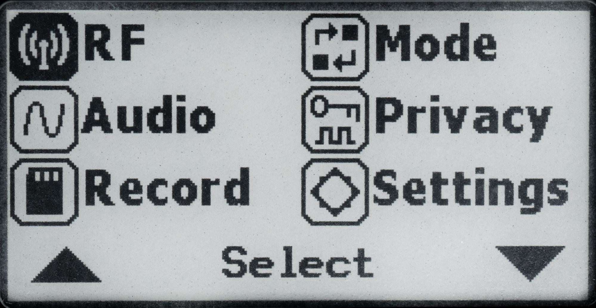
To access the Main menu, open the battery door and press the middle button. Once in the Main Menu:
Select the RF Menu to change the following settings:
Input Type
The A20-TX is compatible with many types of input sources.
The Record menu provides the ability to start and stop recording. When set to RF Only mode, recording is not permitted.
See Recording WAV Files for more information.
Select the Mode menu to choose one of three modes of operation: RF Only mode, Rec Only Mode, or Rec + RF Mode (available to International, non-US models or US models not set to Lav or Guitar input). When set to RF Only mode, ‘Can’t record in RF Only mode’ is displayed in the Record Menu.
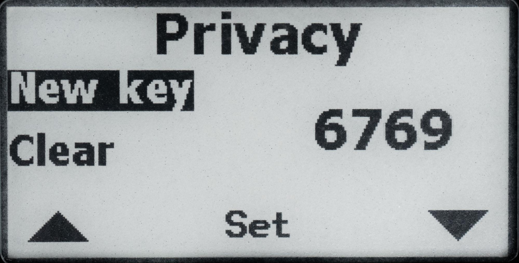
Creates a randomly generated 4-digit privacy key to prevent unauthorized reception of the A20-TX’s transmitted signal. A receiver (A20-Nexus, A20-Nexus Go, or A20-RX) must be set to the same 4-digit key to decode and receive the RF audio.
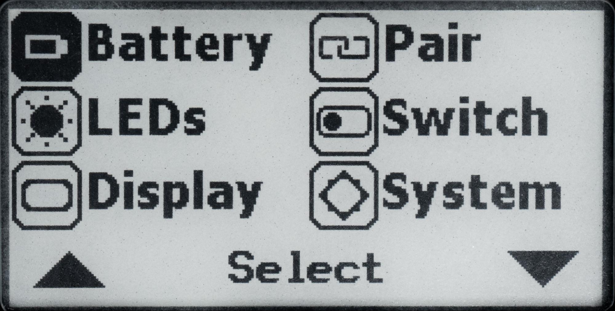
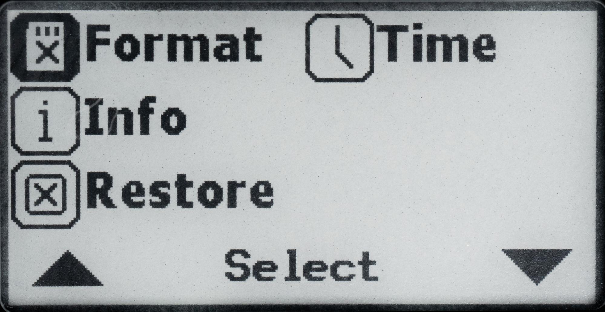
The A20-TX Settings menu provides access to the following menus:
Note: The switch setting is overridden by commands coming from the A20-TX interface, A20-Nexus (via NexLink) or A20-Remote (via Bluetooth), which will leave the switch in the incorrect physical position. As such, it is necessary to move the switch first to the physical position that reflects the A20-TX’s current state before it will perform its next command.
See Installing the Optional Bayonet Switch.
Note:
RF signals transmitted by the A20-TX transmitter are received by the Sound Devices A20-Nexus, A20-Nexus Go, A20-RX and Audio Ltd A10-RX. Set the same modulation and frequency on the transmitter and receiver. See the A20-Nexus, A20-Nexus Go, A20-RX and A10-RX User Guides for more details.
Frequency
The A20-TX transmits on frequencies ranging from 169 MHz – 1525 MHz. The frequencies available are determined by geographic location and whether you have entered a unique license code issued by Sound Devices to unlock the use of restricted frequencies.
Because the A20 digital RF transmission is inherently immune to intermodulation, multiple A20 Digital Wireless transmitters can be used simultaneously on nearby adjacent frequencies without worry of intermodulation interference. Systems can be used together when separated by at least 400 kHz. When operating in the 902-928 MHz Band, it is recommended to separate channel frequencies by at least 1 MHz.
Set the A20-TX’s transmit frequency from the RF > Frequency menu or via A20-Remote or A20-Nexus.
Ensure an antenna with a length specific to the frequency in use is attached to the SMA connector. Using the wrong length of antenna reduces RF range. See Antenna Guide for more information.
Modulation
The A20-TX offers two types of modulation, Long Range and Standard. Long Range modulation has better sensitivity resulting in more robust performance in challenging RF environments. Standard modulation has lower latency (2ms versus the 3.9ms of Long Range). The Modulation setting must match between the A20-TX and A20 receivers, in order for the transmitted signal to be received.
RF Power
RF power is the strength of the transmitting signal. The A20-TX offers the following RF power settings:
Set the A20-TX’s RF Power from the RF > RF Power menu or via A20-Remote or A20-Nexus.
RF Power settings are based on the selected Country of the device running A20-Remote as some legal restrictions may apply.
In situations where the transmitter is relatively close to the receiver, the Low - 2 mW setting offers good range and best battery life.
For most common wireless microphone applications, the Normal - 10 mW setting provides excellent range. In situations where body absorption may be an issue or extended range is required, the High - 20 mW setting can be helpful.
If significant body absorption is unavoidable or maximum range is required, the Extra High - 40 mW setting can be enabled via the Settings menu. Please be aware that the Extra High - 40 mW RF Power setting can reduce battery life by over 20%.
Tip: Use Long Range Modulation to increase RF range prior to increasing the RF Power setting.
The A20-TX transmitter supports GainForward, a technology that eliminates the need to adjust microphone preamplifier gain at the wireless transmitter. Audio levels from the transmitter are controlled either directly at the mixer’s digital trim control or at the wireless receiver. If the source is too soft or too loud, adjust the transmitter’s audio level with a downstream mixer’s digital trim gain control. There is absolutely no noise penalty when the audio path remains 100% digital, i.e. A20 transmitter -> A20 receiver, A20 receiver digital audio output -> mixer digital audio input. Read more about GainForward at:
https://www.sounddevices.com/gainforward-explained/
Adjusting Audio of the A20-TX Signal from the A20-RX and A10-RX Receiver
From the A20-RX or A10-RX home screen, press the channel’s arrow button twice to enter the Input menu. From the Input menu, press the middle button to select a sub-menu to adjust gain, low cut, or limiter of the incoming A20-TX transmitted signal.
Gain is adjustable from 0 to 60 dB. Low cut can be set to Off, 40 Hz, 60 Hz, 80 Hz, 100 Hz, or 200 Hz. Limiter can be turned on or off. The information menu displays the status of the tuned A20-TX. See the A20-RX or A10-RX User Guides for more details.
Adjusting Audio of the A20-TX Signal from the A20-Nexus or A20-Nexus Go Receiver
See the A20-Nexus and A20-Nexus Go User Guides for details.
Adjusting Audio of the A20-TX Signal from the 8-Series or 688
When the A20-RX or A10-RX receiving A20-TX signal is slotted into the SL-2 or SL-6, the A20-RX or A10-RX Input menu settings are bypassed and all gain, low cut, and limiter activity are performed and controlled by the 688, 833, 888, or Scorpio. This is also the case when using an A20-Nexus or A20-Nexus Go docked to an 8-Series. See the Mixer-Recorder User Guides for more information.
The A20-TX records 32-bit float Broadcast WAV (under 4 GB) or RF64 WAV (over 4 GB) files at 48 kHz sampling rates to a removable micro SD card (not included). 32-bit float files are recorded such that gain decisions can be made after recording. Because of the high dynamic range of the A20-TX, audio levels are never too high or too low. Learn more about 32-bit float at:
https://www.sounddevices.com/A20-TX-32-bit-float-recording
A20-TX recordings are started and stopped using the record and stop buttons in the A20-Remote Transmitter View, from A20-Nexus/A20-Nexus Go, or from the A20-TX’s Record menu. Additionally, the A20-TX Switch, an optional bayonet switch, can be fitted to the A20-TX and programmed to start and stop recording.
The file name format of recorded files is: transmitter name-YYMMDDHHMMSS.WAV. For example, if the A20-TX name has been changed to “Barney” and a recording is created on July 10, 2021 at 09:30 (24 hour format), the resulting file is named Barney-210710093000.WAV. All files are recorded at the root of the media (no folders).
About recording formats:
The A20-TX can be jammed wirelessly via NexLink from the A20-Nexus, A20-Nexus Go, or from cabled external timecode sources. The timecode value and frame rate are taken from the incoming LTC source. If timecode has not been jammed, the A20-TX starts rolling timecode from 00:00:00:00 when it is powered on.
Jammed timecode values are held for up to four hours after powering off, and up to one hour after the battery has been removed. This allows for time to swap batteries without having to re-jam timecode.
When the A20-TX is powered off with a charged battery inserted, the Audio/Timecode LED flashes blue on the 00 frame crossing to indicate timecode is being held.
To jam timecode via cable, connect a valid LTC source using one of the optional accessories, Sound Devices XL-TC-USBC-LEMO or XL-TC-USBC-BNC, to the A20-TX USB-C port. Timecode is automatically jammed once a valid LTC source is connected. After a successful timecode jam, the Audio/Timecode LED flashes blue on the 00 frame crossing.
Timecode is output from the USB-C using the Sound Devices XL-TC-USBC-LEMO, so you can verify that the A20-TX timecode is in sync with the LTC source. The Audio/Timecode LED stops flashing blue when USB-C is disconnected.
For more information about the A20-TX timecode accessory cables visit:
https://www.sounddevices.com/product/xl-tc-usbc-bnc/
https://www.sounddevices.com/product/xl-tc-usbc-lemo/
A20-TX can also jam timecode from 8-Series Mixer-Recorders using a standard USB-C to USB-A cable. Connect the A20-TX to the 8-Series USB-A port. Enter the 8-Series Menu > Timecode/Sync > Jam A20 Transmitter then select Jam A20. The 8-Series Jam A20 Transmitter menu displays the current timecode frame rate and values for the 8-Series and A20-TX and displays the difference between the two units.
The A20-TX connects via USB-C to a computer as an exFAT-formatted mass storage device. Copy WAV files from the
A20-TX to the computer. When file transfer is complete, eject the drive from the operating system and disconnect USB.
Recording must be stopped on the A20-TX before connecting to the computer. While connected to a computer, RF transmission, audio, and recording are disabled.
Register your A20-TX to stay informed of firmware updates. https://my.sounddevices.com/
To update your A20-TX firmware:
https://www.sounddevices.com/download/?prod=A20-TX
At this point, ‘Updating firmware. Please wait …’ is displayed and all the LEDs “dance” to indicate the firmware update is in progress. Once the update is completed, “Update successful. Rebooting …’ is displayed and the A20-TX reboots. The firmware update can take a few minutes to complete.
When the firmware update completes, the A20-TX automatically deletes the PRG file from the media. Firmware version information is displayed in A20-Remote Manage Transmitter view, the Transmitter View Information menu, and in the A20-Nexus TX List >TX Info view.
A20-Remote is an application for Android/iOS phones and tablets designed to pair with A20 (A20-TX, A20-Mini) transmitters. All transmitter settings are conveniently controlled using A20-Remote.
When connected via Bluetooth LE to the A20-TX, A20-Remote offers control and display of all A20-TX parameters, including:
Download and install the A20-Remote app from the Google Play Store or Apple App Store.
https://www.sounddevices.com/a20-remote
A20-Remote has the following minimum operating requirements: Android tablets and phones running Android 8+, or
iPad and iOS devices running iOS 13+. The device must have Bluetooth and Location Services on in order to connect with an A20 Transmitter.
IMPORTANT: The mobile device’s location is used to determine available frequencies, RF power levels, and TV channel mapping of the A20 transmitter. The Country setting is automatically set using the mobile device’s Location Services.
The mobile device’s system date and time are used in the metadata of recorded files.
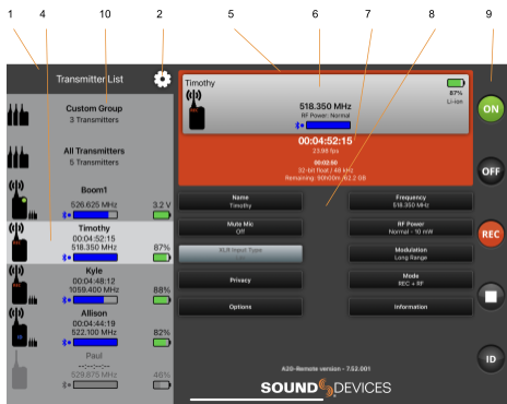
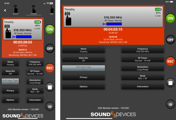
Tablet View
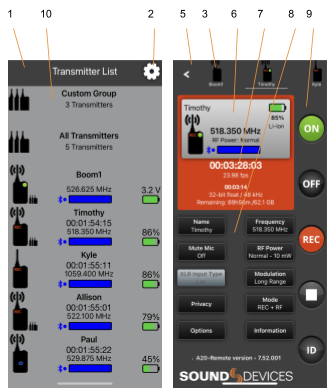
Phone View
1: Transmitter List
Scroll to see all available transmitters in the Transmitter List. Touch a transmitter or transmitter group to display the Transmitter View or Group View. Transmitters that are enabled from Manage Transmitters appear in the Transmitter List. See Transmitter List for more details.
2: Manage Transmitters
Touch the Gear icon to access Manage Transmitters. From Manage Transmitters, pair transmitters, enable transmitters, set Country, set up groups, unlock Restricted Frequencies, access A20 Transmitter User Guides, and view A20-Remote version information.
3: Transmitter Quick List (Phone View Only)
From a phone, the Transmitter List and Transmitter View are not displayed simultaneously. The Quick List is a simplified version of the Transmitter List allowing for quick selection of transmitters from the Transmitter View. The list is horizontally scrollable and lists transmitters by name with their Status indicator. Touch the Back button to return to the Transmitter List.
4: Active Transmitter or Group
Touch any transmitter or Group in the Transmitter List to make it the active view. From a tablet, the highlighted transmitter or group in the Transmitter List indicates the active transmitter or group shown in the Transmitter View displayed on the right-hand side of the app. From a phone, the active transmitter or group is the one displayed in the Transmitter View and underlined in the Transmitter Quick List.
5: Transmitter View
Displays the active transmitter’s status window and provides access to the transmitter’s menus and controls.
6: Transmitter Status Window
Displays the active transmitter’s name, transmitter status, battery life, power source, frequency, RF power level, licensed frequency icon, and Bluetooth signal strength meter.
7: Record and Timecode Window
Displays the current timecode value, frame rate, absolute time of recording, and the remaining time and space of media. The window is red when the transmitter is actively recording. This window is not displayed when the A20 transmitter Mode is set to RF Only.
8: Transmitter Menu
This menu offers control of the A20 transmitter Name, Frequency, Mute Mic, RF Power, XLR Input Type (A20-TX only), Modulation, Privacy, Mode, Options, and access to A20 transmitter Information.
9: Transmitter Controls
Allows control of the active transmitter’s Power On, Power Off, Record, Stop, and Identify mode.
10: Transmitter Groups, Group View
See Group Control for details.
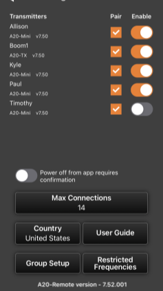
Manage Transmitters is the first page displayed when launching the A20-Remote app if no transmitters have been paired to the mobile device.
Manage Transmitters displays all A20 transmitters within range that are in Pairing mode and any that have been previously paired to the mobile device. Transmitters appear in Manage Transmitters with transmitter name and current firmware version. Paired transmitters that are not within Bluetooth range or are connected to another device are displayed in italics and the Enable switch is grayed out. Enter Manage Transmitters at any time by touching the Transmitter List gear icon.
Pairing an A20-TX with A20-Remote
Access the A20-TX’s Settings > Pair menu to put the A20-TX into pairing mode. While in the process of pairing, ‘Pairing. Please wait …’ is displayed and the right top panel LED flashes blue. Make sure all instances of A20-Remote are fully closed on other mobile devices before attempting to pair to a new device.
From A20-Remote’s Manage Transmitters window, touch the Pair box to add a checkmark and pair the A20-TX to the mobile device. The A20-TX exits Pairing mode once it has been paired with the mobile device. Agree to the Terms and Conditions displayed in the app to continue. Once paired, the A20-TX’s screen exits back to the home screen and its top panel LED stops flashing blue.
To unpair/remove an A20-TX from the mobile device, touch the Pair box to clear the checkmark. Once removed, repeat the pairing process to re-add the transmitter.
Enabling A20 Transmitters for Control
From the A20-Remote Manage Transmitter window, enable an A20 transmitter for control using the Enable switch. Enabled transmitters are added to the Transmitter List and can be controlled from A20-Remote. Since only one mobile device can be used to control an A20 transmitter at a time, be sure to disable the Enable switch prior to handing over control from one mobile device to another.
Power off from app requires confirmation
When ‘Power off from app requires confirmation’ is active, touching the Power button in the Transmitter View displays a confirmation pop-up to avoid accidentally powering off an A20 transmitter. Deactivate this option when you want the Power button to power off A20 transmitters without confirmation.
Max Connections
All mobile devices have a maximum number of supported Bluetooth devices (smartwatches, headphones etc) that they can connect to simultaneously. The maximum number of simultaneous connections is dependent on iOS/Android hardware and operating system version. When A20-Remote attempts to control A20 transmitters exceeding the maximum number of supported simultaneous connections by the mobile device, there is the potential for communication errors.
The Max Connections setting enables A20-Remote to maintain reliable Bluetooth communication with all transmitters in situations where there are more transmitters than the maximum number allowed by the mobile device. It does this by automatically staggering communication. The top transmitters in the Transmitter List are treated as priority, then communication steps through the remaining transmitters on the list, one at a time. All of this is managed automatically by A20-Remote.
Determining the Max Connections Value:
Start by setting Max Connections to 7.
If A20-Remote is able to simultaneously connect to 7 transmitters, then try setting a higher Max Connections value.
If A20-Remote is unable to simultaneously connect to 7 transmitters, the following warning is displayed:
Connection Failed
[A20-Mini name] failed to connect.
Consider reducing Max Connections to 6
Reduce Max Connections to 6. If the ‘Connection Failed’ warning keeps being displayed, then decrease Max Connections until the warning no longer appears.
A transmitter has an active simultaneous connection if a dot is displayed between the transmitter’s Bluetooth symbol and signal strength meter.
The maximum number of available connections is dependent on all Bluetooth devices currently connected to the smartphone/tablet. For this reason, it may be necessary to change Max Connections from time to time and/or disconnect other bluetooth devices (such as watches, headphones, smart speakers, etc.) not currently in use.
Country
Country is automatically set by Location Services of the mobile device. The Country setting determines available frequencies and RF Power options. It is the user’s responsibility to operate on allowed frequencies in their region. Make sure to set A20-Nexus, A20-Nexus Go, and A20-RX receivers to the same country as the A20 transmitters.
Group Setup
Enters the Group Setup menu. See Group Control for more information.
User Guides
Touch to open the User Guide selection view with links to the A20-TX and A20-Mini User Guides.
Restricted Frequencies
The wireless system operator needs to be aware of local regulations and comply with all applicable laws regarding operation of wireless devices.
The Manage Restricted Frequencies menu allows the unlocking of restricted frequencies that require proof of a valid license before they can be used. Once a license has been granted, please contact Sound Devices ([email protected]) to obtain the necessary unlock code. The license will be applied to the unique device ID provided to Sound Devices. Tap the Check for Licenses button or manually enter the License Code to unlock the restricted frequencies.
An example of a frequency band requiring an unlock code in the United States is 1435-1525 MHz. Program Making and Special Events (PMSE) wireless operators typically call 1435-1525 MHz the "AFTRCC band". AFTRCC stands for Aerospace and Flight Test Radio Coordinating Council. This organization coordinates a number of frequency bands for use by air and spacecraft in the United States. This includes 1435-1525 MHz.
Per the United States Federal Communications Commission (FCC) rules, wireless microphones are allowed as secondary users in the 1435-1525 MHz AFTRCC band. This is detailed in the FCC Part 74 rules:
https://www.ecfr.gov/current/title-47/chapter-I/subchapter-C/part-74
One section of the Part 74 rules that is of particular interest to operators seeking an AFTRCC band license is 74.803(d):
https://www.ecfr.gov/current/title-47/chapter-I/subchapter-C/part-74#p-74.803(d)
Similar to the 914.5 - 944 MHz band,nationwide licenses are not typically granted for wireless operation in 1435-1525 MHz.
Generally speaking, a wireless operator needs to show they've used all other available spectrum before the AFTRCC will consider a license request in the 1435-1525 MHz range. If granted, the license is normally assigned for a specific location and a specific time range.
Sound Devices encourages all wireless operators to obtain a Part 74 license, and specifically to make sure applicable parts of the 600 MHz and 950 MHz range are included with their license application. This can help show an operator is aware of the available spectrum and is utilizing it responsibly.
More information on Part 74 licensing can be found here: https://www.local695.com/fcc-licensing/
A20-Remote Version
Displays the current A20-Remote software version.
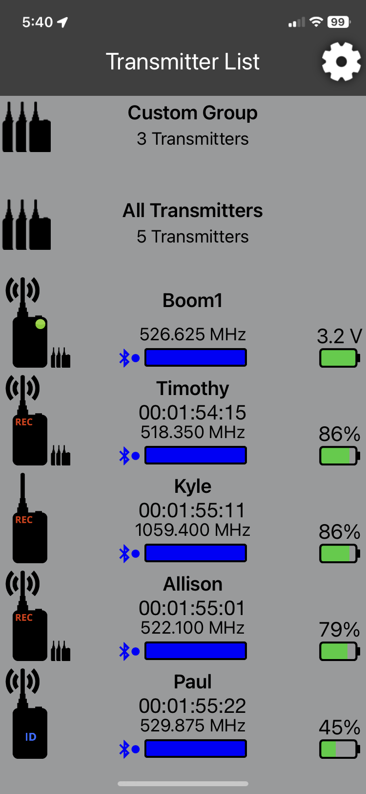
The Transmitter List is a scrollable list of Groups and all enabled A20 transmitters.
Groups appear at the top of the Transmitter List. The All Transmitter and custom groups can be removed from the Transmitter List in Group Setup.
Each transmitter is listed with a high-level view of the transmitter’s status. This includes the transmitter’s name, set frequency, Bluetooth signal strength meter, the status of battery level/charging, custom Group assignment, and an A20 transmitter Status indicator that displays the status of the A20 transmitter’s power, audio presence/mute, record, RF transmission, and Identify mode.
A20 Transmitter Status Indicator
Icon | Description |
On The A20 transmitter appears black when it is on. | |
Recording The letters “REC” appear in red in the top left corner when the A20 transmitter is recording. | |
Transmitting RF The A20 transmitter appears with RF waves coming from the antenna when it is transmitting RF. | |
Audio Presence The A20 transmitter appears with a green circle in the top right corner when audio is present. | |
Mic Muted The A20 transmitter appears with a blue circle in the top right corner when it is muted. | |
Recording, Transmitting, Audio The A20 transmitter is on, recording, transmitting RF, and audio is present. | |
Identify Mode The A20 transmitter appears with a flashing ‘ID’ when the unit is in Identify mode. | |
Off The A20 transmitter appears gray when it is powered off. | |
Off, Holding Timecode The A20 transmitter appears gray with “TC” in blue when it is powered off and holding timecode. | |
Unknown State The A20 transmitter appears with ‘?’ when the status is unknown. This could be displayed because the unit is out of range or the power source has been removed or depleted. |
Custom Group Indicator
The Custom Group indicator displays when the A20 transmitter is a member of the custom group. See Group Control for more information.
Bluetooth Signal Strength Indicator
Displays the signal strength of the A20 transmitter Bluetooth signal received by the mobile device. The Bluetooth meter border is red when the mobile device is not communicating with the transmitter. A blue dot appears after the Bluetooth icon when the transmitter is connected.
Battery/Power Status Indicator
Icon | Description |
Battery Level Indicator Displays the level of the battery. Green = Good Orange = Marginal, about an hour of battery life remaining. Red = Low, 15-20 minutes of battery life remaining. Flashing Red = Critically low, RF, audio, and recording disabled. Battery level is displayed directly above the battery icon as a voltage. It is normal to see voltages increase for the first 60-90 minutes when fresh Energizer Lithium primary AA cells are put under load. This is due to the characteristic of the cells gradually warming up, raising the terminal voltage. | |
Battery Charge Indicator Displays the charging status of the battery. Orange = Charging Green = Charging complete | |
USB Power Displays when USB is powering the A20-TX and there are no batteries inserted. |
Transmitter Name
Displays the name of the A20 transmitter. The serial number is the default name. The name can be changed in the Transmitter View menu.
Transmitter Timecode
Displays the timecode values in hours:minutes:seconds:frames of the connected transmitter. This allows you to quickly see that the connected A20 transmitters are running the same timecode. It is normal to observe a few frames difference between transmitter timecode displays.
If the transmitter is either off or not connected, timecode values are displayed as --:--:--:--. Timecode values are not displayed in RF Only mode.
Transmitter Frequency
Displays the RF frequency on which the A20 transmitter is transmitting. The RF frequency can be changed in the Transmitter View menu.
Reordering the Transmitter List
Reorder Transmitter List by pressing and holding an A20 transmitter, then dragging it into the desired position. Groups cannot be reordered. Groups can be removed from the Transmitter List in the Group Setup menu.
The Transmitter View displays detailed information, controls, and menus for the selected A20 transmitter.
Active A20 Transmitter in the Transmitter View
The active A20-TX in the Transmitter View is indicated by the highlighted entry of the Transmitter List. Touch any transmitter in the Transmitter List to make it the active transmitter.
Quick List (Phone Only)
The Quick List is a horizontally scrollable list of all enabled A20 transmitters along with their Status indicator and transmitter name. Touch a transmitter on the Quick List to make it the active transmitter in the Transmitter View. Touch the back button to exit back to the Transmitter List.
Transmitter Status Window
The Transmitter Status window displays detailed information of the active transmitter. The A20 transmitter Status indicator, Battery /Power status indicator, and Bluetooth Signal Strength meter are described in detail in the Transmitter List section. These indicators are also present in the Transmitter Status window. In addition, the Transmitter Status window shows the active power source and RF Transmission details.
Power Source Details
The battery level meter, battery voltage (‘%’ if the transmitter is an A20-Mini that is powered by NP-BX1), and battery chemistry are displayed in the top right corner of the Transmitter Status Window. USB is displayed when powering the A20 transmitter from USB-C.
RF Transmission Details
RF Transmission details are displayed when the A20 transmitter mode is set to RF Only or REC + RF (not available in the U.S with lav or guitar input sources).
The set frequency is displayed in MHz and the RF Power setting is listed below.
License Required
Some frequencies may require a license to operate on in your area. The License icon appears as a reminder to the user if the set frequency requires a license for the current Country.
Recording & Timecode Status Window
Recording & Timecode details are displayed when A20 transmitter mode is set to REC Only or REC + RF (not available in the U.S with lav or guitar input sources).
Timecode values, frame rate, absolute record time counter, file format (32-bit float, 48 kHz), and remaining record time / space of the media. This window is red when recording.
Controlling the A20 Transmitter from A20-Remote
From the Transmitter View you can control parameters of the A20 transmitter while it is powered on. The transmitter continues to communicate with the app when powered off. While off, the A20 transmitter’s current settings are displayed. The transmitter can be powered on or put into Identify mode from the app while it is powered off.
Transmitter Controls
The far right-hand side of the Transmitter View provides easy access to Power, Identify mode, Record, and Stop.
Icon | Description |
Transmitter Power On Touch the Power ON button to power the A20 transmitter on. The button is black when the transmitter is off and green when on. | |
Transmitter Power Off Touch the Power OFF button to power the A20 transmitter off. The button is gray when the transmitter is off and black when on. By default, a confirmation pop-up message appears when powering off the A20 transmitter from the app. This can be deactivated in ‘Manage Transmitters’ by deactivating ‘Power off from app requires confirmation’. | |
Record Touch the Record button to start recording. The button is red while recording. The button is gray when recording is not permitted. | |
Stop Touch the Stop button to stop recording. The button is yellow while recording is stopped. The button is gray when recording is not permitted. | |
Identify Mode Touch the Identify button to put the A20 transmitter into Identify mode. The transmitter vibrates and all its LEDs rapidly alternate red, green, blue, making it easy to locate. When Identify mode is active, the Identify button flashes blue and the transmitter Status indicator shows “ID” in blue text. Touch the Identify button again or press the A20-TX power button to disable Identify mode. Identify mode is available when A20 transmitters are powered on or off. |
Transmitter Menu
The Transmitter Menu is displayed beneath the Transmitter and Record & Timecode Status windows of the Transmitter View. It offers control of the A20-TX Name, Frequency, Mute Mic, RF Power, Audio input Type, Modulation, Privacy, Mode, Options, and access A20-TX Information.
Name
While in the Transmitter View, touch the Name button and use the pop-up QWERTY keyboard to rename the transmitter. Up to twelve alphanumeric characters can be used for the transmitter’s name. The serial number of the unit is the name by default. Transmitter names are sent to the A20-Nexus, A20-Nexus Go, A20-RX, and A10-RX, and are embedded in metadata as the Track Names of recorded WAV files.
Frequency
Touch the Frequency button to enter the Frequency menu. From the frequency menu, use the scroll wheels to select a frequency (integer and fractional of MHz) or use the +400 kHz and -400 kHz buttons. Touch the ‘Set Frequency’ button to set the frequency and exit back to the Transmitter View.
Ensure an antenna with a length specific to the frequency in use is attached to the SMA connector. Using the wrong length of antenna reduces RF range. See Antenna Guide for more information.
RF Power
A20 transmitters offer the following RF power settings:
Tip: Use Long Range Modulation to increase RF range before considering increasing the RF Power setting.
Modulation
Select Standard or Long Range Modulation. When compared to Standard Modulation, Long Range Modulation has better sensitivity. This increased sensitivity results in more robust performance in challenging RF environments.
The Modulation setting must match between the A20 transmitter and A20 receiver in order for the transmitted signal to be received.
Mode
Touch the Mode button to enter the Mode menu. Select between RF Only, REC Only, and REC + RF.
When Audio Input Type is set to Lav or Guitar, Simultaneous Record and Transmit mode is not available on A20-TX units sold or operated in the United States of America.
Record & Timecode details are not displayed in the TX Status Window when ‘RF Only’ is selected. RF Transmission details are not displayed in the Transmitter Status window when REC Only is selected.
Mute Mic
Touch the Mute Mic button to mute the microphone. When muted, no audio is present in the recordings or transmitted. Mute status is indicated by a blue Mute Mic menu button, a blue dot in the A20 transmitter Status indicator, and the A20 transmitter Audio and Status LEDs turn solid blue.
XLR Input Type
Touch the XLR Input Type button to select the balanced XLR Input Type. When a Lav or Guitar is connected, the A20-TX’s XLR Input Type is automatically set and the button is grayed out. See Audio for more information.
Privacy
Touch the Privacy button to generate or clear a privacy key.
Information
Displays the recommended antenna and TV Channel (where applicable) of the set frequency, the A20 transmitter’s firmware version and serial number, and compliance documentation for local government requirements, if applicable.
Options
The Options menu provides access to a sub-menu of less frequently changed A20-TX settings.
Auto-Power with Lemo Connection
A20 transmitters can auto-detect the presence of a lavalier microphone connection and power on and off accordingly. When ‘Auto-power with Lemo Connection’ is active, connecting a lavalier microphone to the A20 transmitter automatically powers the transmitter on. Removing the lavalier mic connection automatically powers the transmitter off. This feature can be turned on or off.
Resume Record Upon Powering On
When ‘Resume record state upon powering on’ is active, the A20 transmitter resumes the state of the recorder when it was powered off. This menu item is not available when in RF Only mode.
Allow Extra High RF Power
Activate this option when you want the Extra High - 40 mW setting available in the RF Power menu. See RF Power for more information.
A20-TX Switch
Determines the function of the optional bayonet-style A20-TX on/off witch. Select from:
Display
Accesses settings pertaining to the A20-TX e-Paper display
LEDs
The A20-TX front and top panel LEDs can be turned on or off. Turn the LEDs off when you need the A20-TX to be discreet.
Select which LEDs are enabled:
Battery Chemistry
To ensure accurate battery level threshold monitoring (green, orange, red, flashing red, and shutdown voltage), set the chemistry to match the type of battery being used.
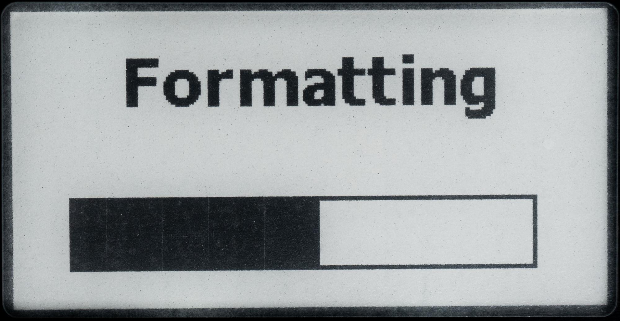
Format Media
Formatting the A20-TX micro-SD card deletes all recorded files. It is good practice to periodically format the micro-SD card. Make certain to transfer any files before formatting. The first eleven characters of the transmitter name are used as the volume name of the micro-SD card.
Restore Defaults
Touch the Restore Defaults button to restore the A20-TX’s default settings.
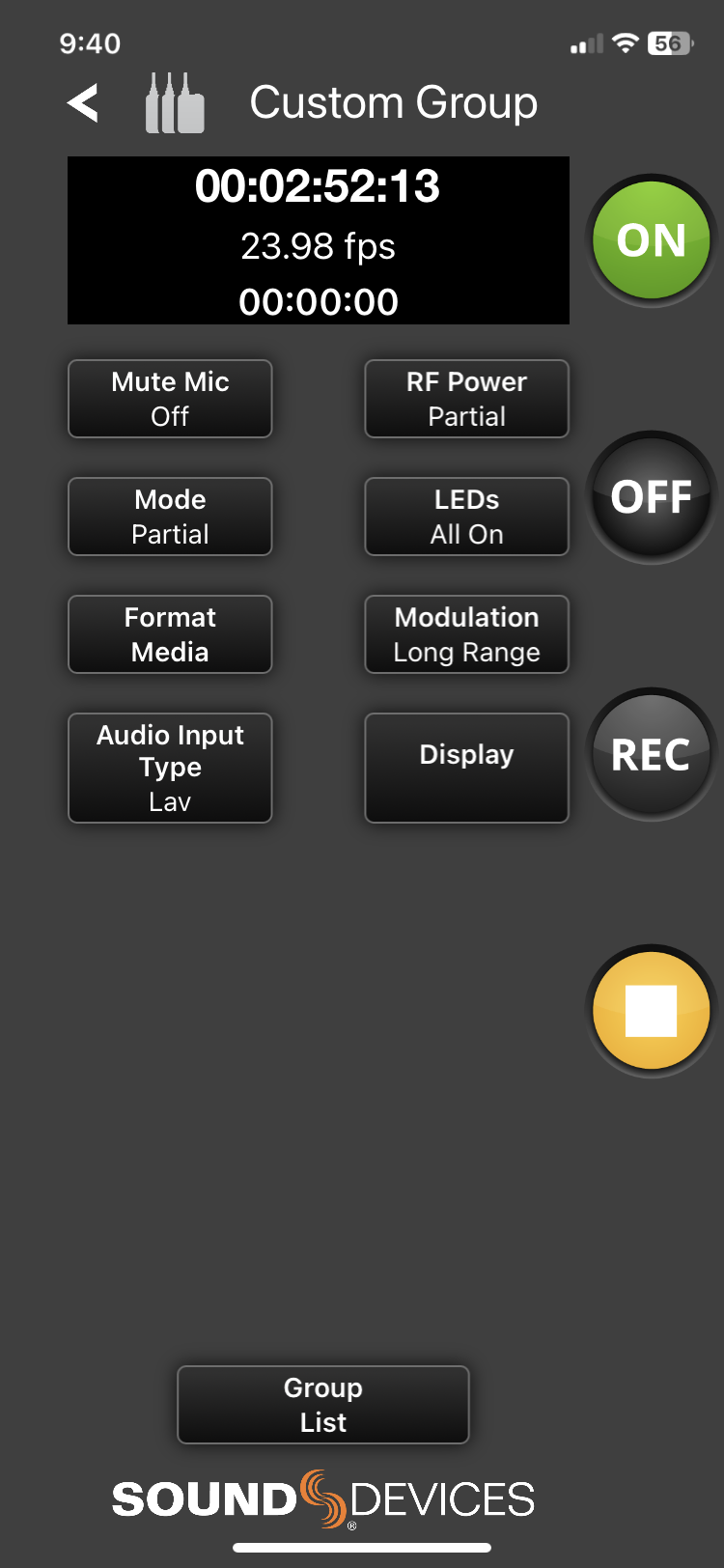
Multiple A20 transmitters can be controlled as a group from the A20-Remote app. Group Control drastically simplifies the workflow and saves time when changing powering and record status of multiple A20 transmitters.
Two groups are available: All Transmitters group for controlling all enabled transmitters and a custom group for controlling a select group of transmitters.
Groups appear at the top of the Transmitter List. When selected, the Group View is displayed. The Group View displays the status of all transmitters in the group and provides group control of the following functions:
Navigate to Manage Transmitters > Group Setup to change group options and create a custom group.
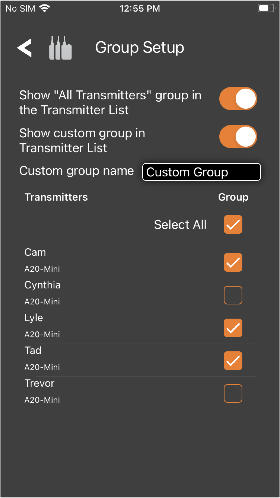
Show “All Transmitters” Group in the Transmitter List
When active, the All Transmitters group is displayed and accessible from the Transmitter List. Deactivate to remove the All Transmitters group from the Transmitter List.
Show Custom Group in the Transmitter List
When active, the custom group is displayed and accessible from the Transmitter List. Deactivate to remove the custom group from the Transmitter List.
Custom Group Name
Touch the text box and use the pop up QWERTY keyboard to rename the custom group. Up to twelve alpha-numeric characters can be used for the custom group name. Custom Group is the name by default.
Assigning A20 Transmitters to the Custom Group
All A20 transmitters paired to the A20-Remote application are displayed in the Group Setup list. Touch the Group checkbox to assign or unassign an A20 transmitter to the custom group.
Use the ‘Select All’ checkbox to assign or unassign all paired transmitters to the custom group. A20 transmitters assigned to the custom group appear with a Custom Group Indicator in the Transmitter List and Transmitter view.
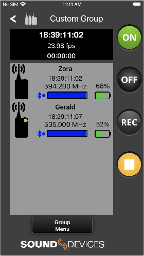
Selecting a Group from the Transmitter List
Groups appear at the top of the Transmitter List. Groups are shown with the number of available transmitters in the group. Touch a group to enter the Group View.
The Group View displays a scrollable list of all available A20 transmitters in the group. Transmitters are displayed with the same information shown in the Transmitter List. Touching a transmitter accesses the A20’s Transmitter View.
The Recording and Timecode window displays timecode, frame rate, and an absolute record time counter. The window is red when recording and black when stopped. This window is not displayed in RF Only mode. The first transmitter of the group list is used to display the details of the Recording and Timecode window.
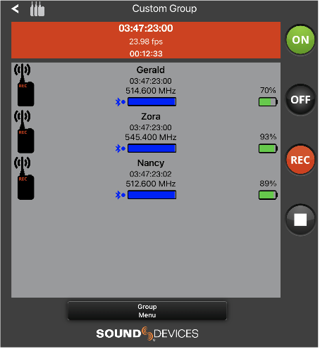
Controlling a Group of A20 Transmitters
Touch any button in the Group View to apply the function to all available transmitters in the group.
Icon | Description |
Group Power On Touch the Group Power ON button to power on the group of transmitters. The button is black when the transmitters are off and green when on. | |
Group Power Off Touch the Group Power OFF button to power off the group of transmitters. The button is gray when the group is off and black when on. By default a confirmation pop-up message appears when powering off A20 transmitters from the app. This can be deactivated in ‘Manage Transmitters’ by deactivating ‘Power off from app requires confirmation’. | |
Group Record Touch the Group Record button to start recording on the group of A20 transmitters. The button is red while the group is recording and black when stopped. The button is gray when recording is not permitted. | |
Group Stop Touch the Group Stop button to stop recording on the group of A20 transmitters. The button is yellow while stopped and black when recording. The button is gray when recording is not permitted. | |
Partial Partial is displayed in between the ON and OFF buttons and in between the Record and Stop buttons when there is a discrepancy between transmitters in the group. For example, if the group is powered on and an individual A20 transmitter is then powered off, “Partial” flashes between the ON and OFF buttons. |
Group Status Screen
A Group Status screen appears while A20-Remote is sending commands to transmitters in the group. The status of the command sent is displayed for each A20 transmitter in the group. The status text is green while sending the command, white when successful, and red if the A20 transmitter was unable to accept the command.
Touch the Cancel button to abort the group command. Canceling a command does not revert any changes already applied and may result with the group in a “Partial” state.
Group Menu
The Group Menu allows you to set Mute, RF Power, Mode, LEDs, Modulation, Audio Input Type, Display (Orientation and Background) and Format Media for all transmitters in the group. Partial is displayed in the menu button when transmitters in the group have different settings.
Touch the Group List button to return to the Group View.
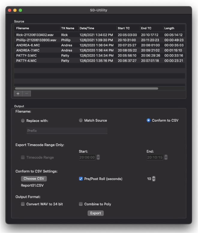
Sound Devices SD-Utility is a companion application for MacOS and Windows that supports Sound Devices wireless products. This application can be used to process files recorded by A20 transmitters to be more suited to the given workflow. A20 transmitter 32-bit float, 48 kHz, monophonic WAV, 2ch polyphonic WAV, and RF64 WAV files can be imported, renamed, snipped by timecode values, converted to 24 bit, conformed to a CSV Sound Report, exported as monophonic or polyphonic WAV, and more.
Installing SD-Utility
Download the SD-Utility Installer for MacOS or Windows from:
https://www.sounddevices.com/download/?prod=sd-utility
Open the installer and install the application by following the on-screen instructions.
Minimum operating requirements:
MacOS 10.11+, 64-bit
Windows 10+, 64-bit
Importing A20 Transmitter Audio Files into SD-Utility
SD-Utility imports the following file types:
There are three methods for importing files into SD-Utility:
The Source window displays the following information for all imported files.
When importing a 2ch polyphonic WAV file from the A20-TX, the file is automatically split into two monophonic WAV files that are stored in a folder called ‘Split Files’. This folder is located in the same volume/directory from which the original files were imported.
Removing WAV files from the Source Window
There are three methods for removing WAV files from the Source window.
Organizing Source Files
Click on an Information Header cell to order the list of files in the Source Window by information. For example, click the Start TC cell to arrange the files by timecode start times from lowest to highest. Click again to reverse the order from highest to lowest.
To manually order the list of source files, click and hold a file row and drag it into the desired position.
Selecting Files to Export
Highlight the file(s) to process and export from the Source window. Multiple files can be selected using keyboard modifiers, Apple and Shift in MacOS, Ctrl and Shift in Windows. If no files are selected, processing is applied to all files in the Source window.
Naming of Processed WAV Files
Processed WAV files will be named according to the Filename selection.
Creating Shorter WAV Files Based on Timecode Range
When a shorter WAV file is needed than the original recording, you can use the Timecode Range feature to create a shorter WAV file. The length and content of the exported file is based on the entered timecode start and stop times.
Conforming A20 Transmitter WAV Files to CSV Sound Reports
CSV sound report files generated by Sound Devices recorders can be used to extract only relevant audio from the A20 transmitter WAV or A10-TX MIC files. Audio is extracted and a new WAV file is created based on the timecode in/out values of takes listed within the CSV.
The exported WAV file names and embedded metadata are changed to match the file names and metadata of the corresponding takes in the CSV sound report.
Adding Pre- and Post-Roll to conformed files can benefit post production with access to audio just prior to and following head and tail slates. To add pre- and post-roll to conformed WAV files, select the Pre/Post Roll checkbox and enter a value from 0 to 10 seconds in 1-second steps.
If the source file does not contain audio data for the duration of the pre- or post-roll location, the exported file will begin and end at the closest point to the pre- and post-roll location where audio data is present.
Selecting Bit Depth of Exported WAV Files
A20 transmitters record 32-bit float WAV files. To convert the WAV files to 24-bit integer, select the ‘Convert WAV to 24 bit’ checkbox. Files that contain audio that exceeds 0 dBFS will be normalized to -0.1 dBFS to avoid clipping when exported as 24-bit.
Combining to Poly
Combine to Poly allows for the export of a single polyphonic WAV file containing audio tracks from each relevant transmitter for takes of the CSV Sound Report or a select timecode range.
Select the Combine to Poly checkbox to export a polyphonic WAV file, leave unchecked to export monophonic WAV files for each transmitter.
Combine to Poly is available with the following setups:
The interleave order of the polyphonic WAV tracks are determined by the order of the files in the Source Window. Silence is written to a track of the exported polyphonic WAV file whenever audio data is not available from the source files.
Specifications are subject to change without prior notice. For the latest information available on all Sound Devices products, visit our website: www.sounddevices.com.
Frequency Range
RF Output Power
Modulation Mode
Antennas
Audio Frequency Response
Audio Input
Menu and Controls
Remote Control
Recording Media
Recording File Format
Simultaneous Record and Transmit mode when using lavalier mic or guitar input is not available on A20-TX units sold or operated in the United States of America.
Timecode
Timecode Clock
Timecode Frame Rates
Frame rates are auto-detected from incoming source
USB-C
Powering
Battery Charging
Battery Runtime
Environmental
Dimensions (H x W x D)
Weight
The A20-TX ships with an antenna set with three antennas (1 straight 470-548 MHz to SMA, 1 straight 548-638 MHz to SMA, 1 straight 17” uncut Astral VHF Whip Antenna to SMA), and set of antenna caps.
Sound Devices offers additional pre-cut and uncut antennas as available options.
Attach antennas with a length specific to the frequency in use. Using the wrong length of antenna reduces RF range.
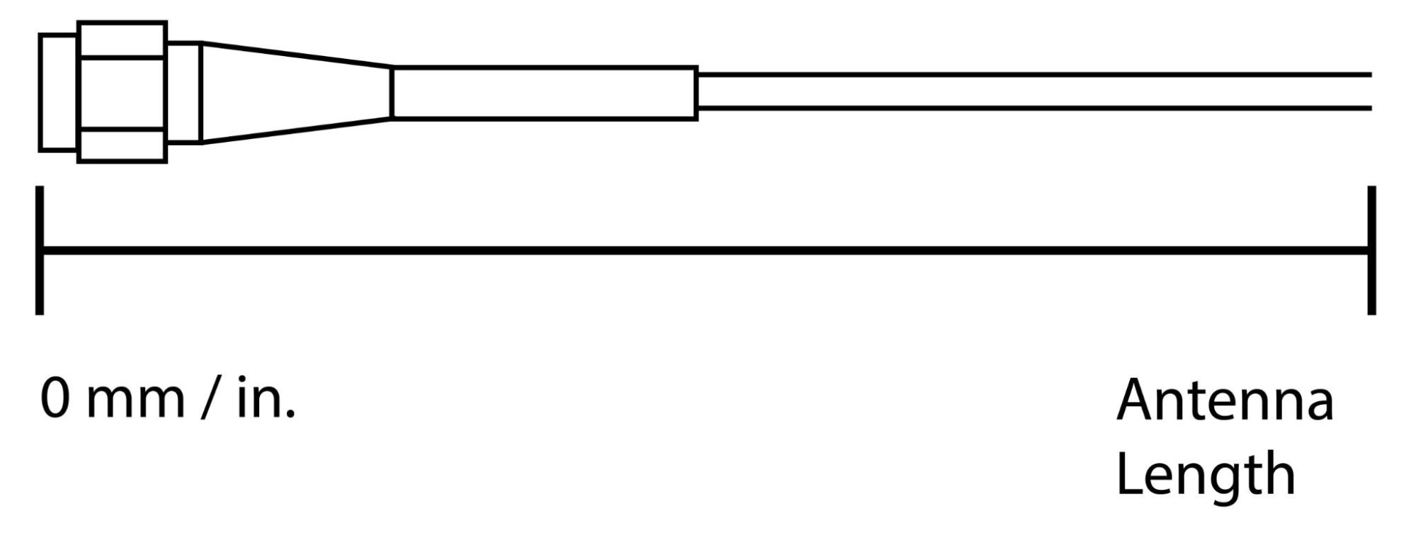
Cutting Antennas to Length
Uncut antennas need to be cut to the length specific to the frequency for intended use.
Antenna Length Chart
Frequency Range | Antenna Length in mm | Antenna Length in inches |
169 - 216 MHz | 388 mm | 15.28” |
470 - 548 MHz | 140 mm | 5.51” |
548 - 663 MHz | 120 mm | 4.72” |
638 - 738 MHz | 104 mm | 4.09” |
738 - 865 MHz | 89 mm | 3.50” |
902 - 1015 MHz | 74 mm | 2.92” |
1045 - 1154 MHz | 65 mm | 2.55” |
1240 - 1260 MHz | 57 mm | 2.24” |
1350 - 1525 MHz | 49 mm | 1.93” |
Do not attempt to service the A20-TX. The case is water-sealed and needs to have new gaskets installed if taken apart. The internal parts are microscopic and not user serviceable. Please send to Sound Devices for any service needs.
https://service.sounddevices.com/contact-support/
Sound Devices, LLC warrants the items listed above against defects in materials and workmanship for a period of ONE (1) year from date of original retail purchase. Users who register their product directly with Sound Devices Technical Support using the online form or by phone, will receive an additional ONE (1) year of warranty coverage, extending the complete warranty period to TWO (2) years from the date of original retail purchase. In order to extend the warranty coverage period, registration must be completed within the initial ONE (1) year warranty period. Products must be purchased through authorized Sound Devices resellers to qualify for Warranty coverage. Damage resulting from the opening of a Sound Devices product or attempted repairs by a non-authorized Sound Devices repair technician will void warranty coverage.
This is a non-transferable warranty that extends only to the original purchaser. Sound Devices, LLC will repair or replace the product at its discretion at no charge. Warranty claims due to severe service conditions will be addressed on an individual basis.
THE WARRANTY AND REMEDIES SET FORTH ABOVE ARE EXCLUSIVE. SOUND DEVICES, LLC DISCLAIMS ALL OTHER WARRANTIES, EXPRESS OR IMPLIED, INCLUDING WARRANTIES OF MERCHANTABILITY AND FITNESS FOR A PARTICULAR PURPOSE. SOUND DEVICES, LLC IS NOT RESPONSIBLE FOR SPECIAL, INCIDENTAL, OR CONSEQUENTIAL DAMAGES ARISING FROM ANY BREACH OF WARRANTY OR UNDER ANY OTHER LEGAL THEORY. Because some jurisdictions do not permit the exclusion or limitations set forth above, they may not apply in all cases.
For all service, including warranty repair, please contact Sound Devices for an RMA (return merchandise authorization) before sending your unit in for repair. Product returned without an RMA number may experience delays in repair. When sending a unit for repair, please do not include accessories, including SSD drives, CF cards, batteries, power supplies, carry cases, cables, or adapters unless instructed by Sound Devices. Sound Devices repairs and replacements may be completed using refurbished, returned or used parts that have been factory certified as functionally equivalent to new parts.
Sound Devices, LLC
Services Repair RMA #XXXXX
E7556 State Road 23 and 33
Reedsburg, WI 53959 USA
Telephone: +1-608-524-0625
The A20-TX includes the following accessories:
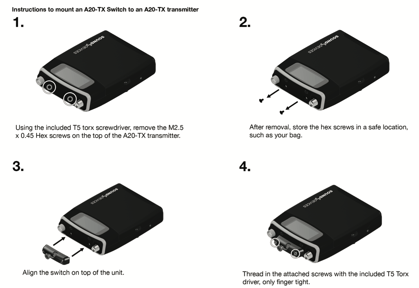
The optional A20-TX Switch is a physical latching on/off bayonet-style switch that mounts to the top of the A20-TX. It can be assigned to the following functions:
The A-BOOM 2 is a boom pole mount designed specifically for the A20-TX transmitter. It mounts to the top of a cabled or cableless boom pole. It can be positioned facing up or down the boom pole, and the onscreen text of the A20-TX screen will conveniently rotate to allow you to read it at the right orientation.
This product is covered under patent number 9,654,134 and other patents pending.
Product specifications and features are subject to change without prior notification. Read and fully understand this manual before operation.
Copyright© 2023 Sound Devices, LLC. All rights reserved. This product is subject to the terms and conditions of a software license agreement provided with the product, and may be used in accordance with the license agreement. This document is protected under copyright law. An authorized licensee of this product may reproduce this publication for the licensee’s own personal use. This document may not be reproduced or distributed, in whole or in part, for commercial purposes, such as selling copies or providing educational services or support. This document is supplied as a technical guide. Special care has been taken in preparing the information for publication; however, since product specifications are subject to change, this document might contain omissions and technical or typographical inaccuracies. Sound Devices, LLC does not accept responsibility for any losses due to the use of this guide.
LIMITATION ON SOUND DEVICES’ LIABILITY. TO THE FULLEST EXTENT PERMITTED BY LAW, SOUND DEVICES SHALL HAVE NO LIABILITY TO THE END USER OR ANY OTHER PERSON FOR COSTS, EXPENSES, DIRECT DAMAGES, INCIDENTAL DAMAGES, PUNITIVE DAMAGES, SPECIAL DAMAGES, CONSEQUENTIAL DAMAGES OR OTHER DAMAGES OF ANY KIND OR NATURE WHATSOEVER ARISING OUT OF OR RELATING TO THE PRODUCTS, THESE TERMS AND CONDITIONS OR THE PARTIES’ RELATIONSHIP, INCLUDING, WITHOUT LIMITATION, DAMAGES RESULTING FROM OR RELATED TO THE DELETION OR OTHER LOSS OF AUDIO RECORDINGS OR DATA, REDUCED OR DIMINISHED AUDIO QUALITY OR OTHER SIMILAR AUDIO DEFECTS ARISING FROM, RELATED TO OR OTHERWISE ATTRIBUTABLE TO THE PRODUCTS OR THE END USER’S USE OR OPERATION THEREOF, REGARDLESS OF WHETHER SUCH DAMAGES ARE CLAIMED UNDER CONTRACT, TORT OR ANY OTHER THEORY. “CONSEQUENTIAL DAMAGES” FOR WHICH SOUND DEVICES SHALL NOT BE LIABLE SHALL INCLUDE, WITHOUT LIMITATION, LOST PROFITS, PENALTIES, DELAY DAMAGES, LIQUIDATED DAMAGES AND OTHER DAMAGES AND LIABILITIES WHICH END USER SHALL BE OBLIGATED TO PAY OR WHICH END USER OR ANY OTHER PARTY MAY INCUR RELATED TO OR ARISING OUT OF ITS CONTRACTS WITH ITS CUSTOMERS OR OTHER THIRD PARTIES. NOTWITHSTANDING AND WITHOUT LIMITING THE FOREGOING, IN NO EVENT SHALL SOUND DEVICES BE LIABLE FOR ANY AMOUNT OF DAMAGES IN EXCESS OF AMOUNTS PAID BY THE END USER FOR THE PRODUCTS AS TO WHICH ANY LIABILITY HAS BEEN DETERMINED TO EXIST. SOUND DEVICES AND END USER EXPRESSLY AGREE THAT THE PRICE FOR THE PRODUCTS WAS DETERMINED IN CONSIDERATION OF THE LIMITATION ON LIABILITY AND DAMAGES SET FORTH HEREIN AND SUCH LIMITATION HAS BEEN SPECIFICALLY BARGAINED FOR AND CONSTITUTES AN AGREED ALLOCATION OF RISK WHICH SHALL SURVIVE THE DETERMINATION OF ANY COURT OF COMPETENT JURISDICTION THAT ANY REMEDY HEREIN FAILS OF ITS ESSENTIAL PURPOSE.
The “wave” logo is a registered trademark of Sound Devices, LLC. Windows is a registered trademark of Microsoft Corporation in the U.S. and other countries. Bluetooth LE is a registered trademark of Bluetooth SIG, Inc. Android is a registered trademark of Google. iPad, iPhone, and iOS are registered trademarks of Apple Inc. All other trademarks herein are the property of their respective owners.
FCC Conformity
This device complies with part 74 and part 15 of the FCC Rules. Operation is subject to the following two conditions:
(1) This device may not cause harmful interference, and
(2) this device must accept any interference received, including interference that may cause undesired operation.
Changes or modifications not expressly approved by the manufacturer could void the user’s authority to operate the equipment.
Warning! Any modifications or changes made to this device, unless explicitly approved by Sound Devices may invalidate the authorization of this device. Operation of an unauthorized device is prohibited under Section 302 of the Communications act of
1934, as amended, and Subpart 1 of Part 2 of Chapter 47 of the Code of Federal Regulations.
FCC Radiation Exposure Statement
This equipment complies with FCC radiation exposure limits set forth for portable conditions. In accordance with FCC requirements, this device has been tested and found to comply with radiation exposure limits for portable conditions, which require a minimum separation distance of 20cm or less between the radiator and your body during operation.
ISED Radiation Exposure Statement
This equipment complies with ISED radiation exposure limits set forth for portable conditions. For safe operation, it must be used in a manner that maintains a separation distance of 20cm or less between the radiator and your body.
Cet équipement est conforme aux limites d'exposition aux rayonnements ISED établies pour des conditions portables. Pour une utilisation sûre, il doit être utilisé de manière à maintenir une distance de séparation de 20 cm ou moins entre le radiateur et votre corps.
FCC Interference Statement
This equipment has been tested and found to comply with the limits for a Class B digital device, pursuant to Part 15 of the FCC Rules. These limits are designed to provide reasonable protection against harmful interference in a residential installation. This equipment generates uses and can radiate radio frequency energy and, if not installed and used in accordance with the instructions, may cause harmful interference to radio communications. However, there is no guarantee that interference will not occur in a particular installation. If this equipment does cause harmful interference to radio or television reception, which can be determined by turning the equipment off and on, the user is encouraged to try to correct the interference by one or more of the following measures:
Industry Canada Conformity
This device operates on a no-interference, no-protection basis. Should the user seek to obtain protection from other radio services operating in the same TV bands, a radio licence is required. For further details, consult Innovation, Science and Economic Development Canada’s Client Procedures Circular CPC-2-1-28, Voluntary Licensing of Licence-Exempt Wireless Microphones in the TV Bands.
This radio transmitter 22225-9808 has been approved by Innovation, Science and Economic Development Canada to operate with the antenna types listed below, with the maximum permissible gain indicated. Antenna types not included in this list that have a gain greater than the maximum gain indicated for any type listed are strictly prohibited for use with this device.
Manufacturer | Description | Maximum Gain | Impedance |
Sound Devices, LLC | Antenna straight 470-548 MHz (140 mm / 5.51”) | +2.15 dBi | 50 ohms |
Sound Devices, LLC | Antenna straight 548-663 MHz (120 mm / 4.72”) | +2.15 dBi | 50 ohms |
Sound Devices, LLC | Antenna straight 902-1015 MHz (74 mm / 2.92”) | +2.15 dBi | 50 ohms |
The transmitter is supplied with the above unique antenna types; to replace a lost, damaged or faulty antenna, please contact Sound Devices, LLC.
This Device complies with Industry Canada Licence-exempt RSS standard(s). Operation is subject to the following two conditions:
1) this device may not cause interference, and
2) this device must accept any interference, including interference that may cause undesired operation of the device.
Conformité à Industrie Canada
Cet appareil opère selon un régime de non-brouillage et de non-protection. Si l’utilisateur veut obtenir une protection par rapport aux autres services radio opérant sur les mêmes bandes TV, une licence radio est requise. Pour plus de détails, veuillez consulter le circulaire de procédures client CPC-2-1-28 Délivrance de licenses sur une base volontaire pour les microphones sans
fils exempts de licence exploités dans les bandes de télévision, publié par Innovation, Sciences et Développement économique Canada.
Ce transmetteur radio 22225-9808 a été approuvé par Innovation, Sciences et Développement économique Canada pour opérer avec les types d’antennes listés ci-dessous, avec gain maximum permissible indiqué. Les types d’antennes non inclus dans cette liste et dont le gain excède le gain maximum indiqué sur n’importe quel type listé ci-dessous sont strictement prohibés d’utilisation avec cet appareil.
Manufacturier | Description | Gain Maximum | Impédance |
Sound Devices, LLC | Antenne droite 470-548 MHz (140 mm / 5.51”) | +2.15 dBi | 50 ohms |
Sound Devices, LLC | Antenne droite 548-638 MHz (120 mm / 4.72”) | +2.15 dBi | 50 ohms |
Sound Devices, LLC | Antenne droite 902-1015 MHz (74 mm / 2.92”) | +2.15 dBi | 50 ohms |
Ce transmetteur est fourni avec les types d’antenne unique ci-dessus; pour remplacer une antenne perdue, endommagée ou défectueuse, veuillez contacter Sound Devices, LLC.
Cet appareil est conforme aux normes CNR exemptes de licence d’Industrie Canada. Son fonctionnement est soumis aux deux conditions suivantes:
1) ce dispositif ne peut pas causer d’interférences, et
2) ce dispositif doit accepter toute interférence, y compris les interférences qui peuvent causer un mauvais fonctionnement de l’appareil.
USA White-Space Operation
For USA operation in the 600 MHz guard band (614-616 MHz) and 600 MHz duplex gap (657 - 663 MHz) users are advised to register with and check a white-space database to determine available channels prior to operation at a given location.
WEEE Statement
If you wish to discard a Sound Devices product in Europe, contact Sound Devices (England) for further information.
Battery Advisory
Incorrect use of batteries poses a danger of explosion. Replace only with the same or equivalent type. Properly recycle batteries. Do not crush, disassemble, incinerate, dispose of in a fire, or expose batteries to high temperatures.
Manufacturer’s Name: Sound Devices, LLC
Manufacturer’s Address: E7556 State Road 23 and 33 Reedsburg, WI 53959 USA
We, Sound Devices, LLC, declare under our sole responsibility that the product
Product Name: A20-TX
Model Number: 9808
Description: Digital Wireless Microphone Transmitter
is in conformity with the essential requirements of the following relevant Union harmonisation legislation:
Radio Equipment Directive (RED) 2014/53/EU
Low Voltage Directive 2014/35/EU
RoHS Directive 2011/65/EU
The following harmonised standards and/or normative documents were applied:
Health & Safety (Article 3.1(a) of RED) EN 62368-1:2014
EN 50566:2017
EMC (Article 3.1(b) of RED) EN 301-489-1 v2.2.3:2019
EN 301-489-9 v2.1.1:2019
EN 301-489-17 v3.2.4:2020
RF Spectrum (Article 3.2 of RED) EN 300 422-1 v2.2.1:2021
EN 300 328 v2.2.2:2019
EN 300 440 v2.1.1:2017
Signed for and on behalf of Sound Devices LLC:
July 20th, 2023
__________________________________ ______________________________________
Date Matt Anderson - Sound Devices, LLC President
A20-TX User Guide