Replacing the 664 & 688 Real-Time Clock Battery
664 & 688 Instructions for Changing the RTC (Real-Time Clock) Battery
664/688 Disassembly
- Observe standard practices and precautions when working with electronic assemblies.
- Work in an ESD safe environment. Ground yourself, tools and equipment to prevent damage from static discharge.
- Remove and/or disconnect power sources from equipment such as AC Adapters and batteries. Allow circuits time to drain any stored charges.
- Disconnect inputs and outputs to prevent connector damage during disassembly and assembly.
- Use proper, well-maintained tools.
NOTE: After servicing the unit, re-assembly should be aided by scrolling through these steps in reverse order to be certain that no small items are missed.
Removing the Top Panel.
NOTE: While the photos in this Tech Note show a 664, these instructions apply equally to the 688.
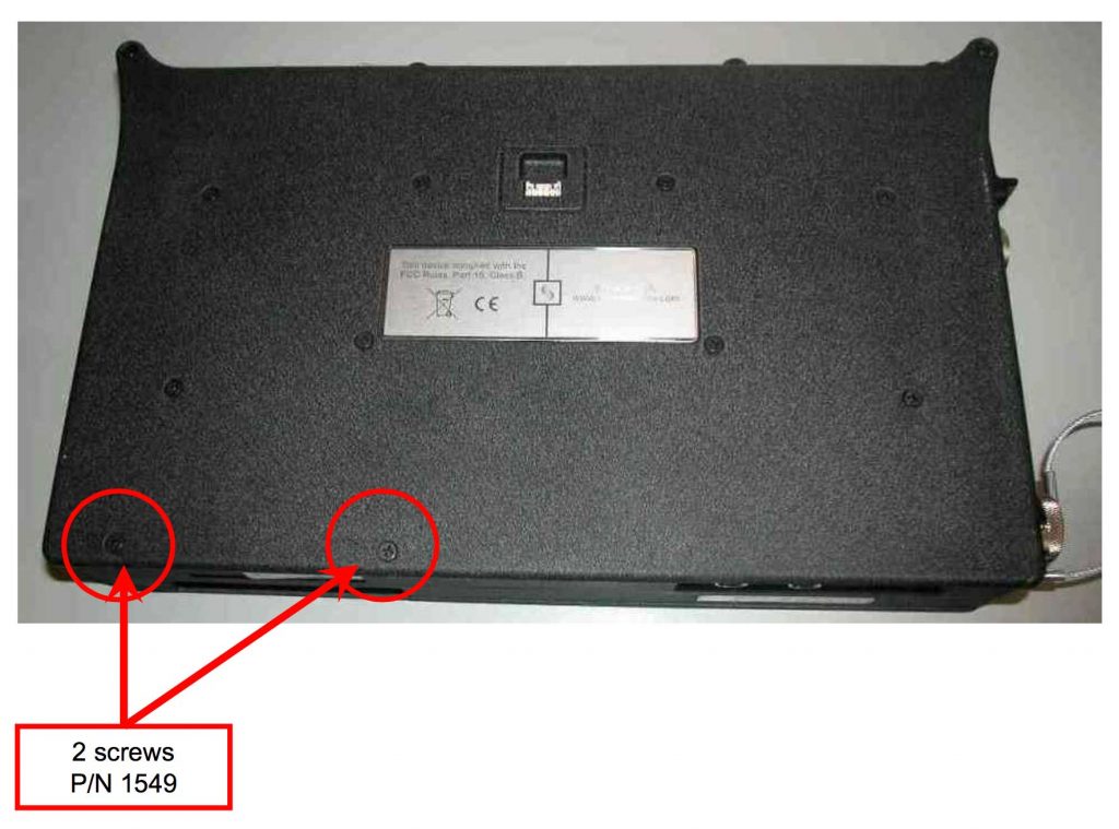
1. Start by turning the unit upside down and removing only the two bottom panel screws nearest to the left end at the back edge.
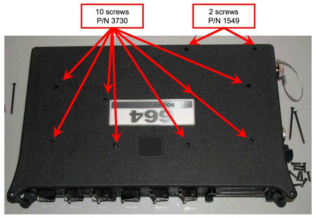
2. Turn the unit right-side up. Remove all twelve top panel screws. Note that the four screws along the back edge (both top and bottom) are much longer; all others are short.
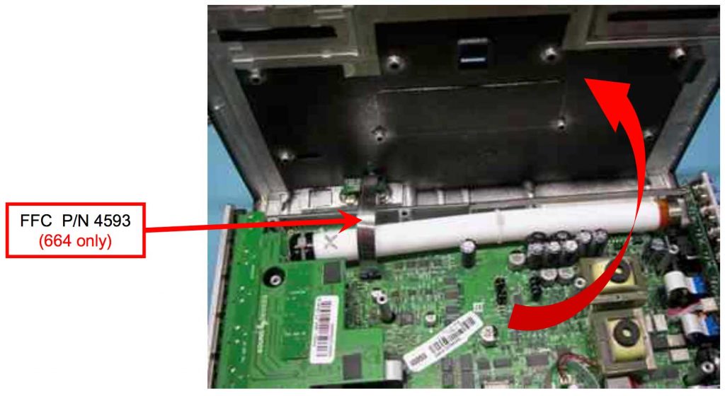
CAUTION: In the next step, you will remove the top panel BUT be aware that a flat flex connector (FFC) connects the main PC board to a small daughter board attached to the top panel. (NOTE: The 688 does not have this FFC.)
3. With that in mind, remove the top panel with some gentle coaxing to separate the snug fit and tilt it back but don’t stress the 664’s FFC. Place something soft (small pillow) behind the panel so that it can’t fall back and damage the FFC. The 668’s top panel can be set aside.
Remove RTC Battery
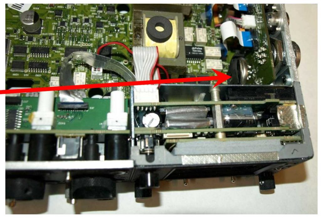
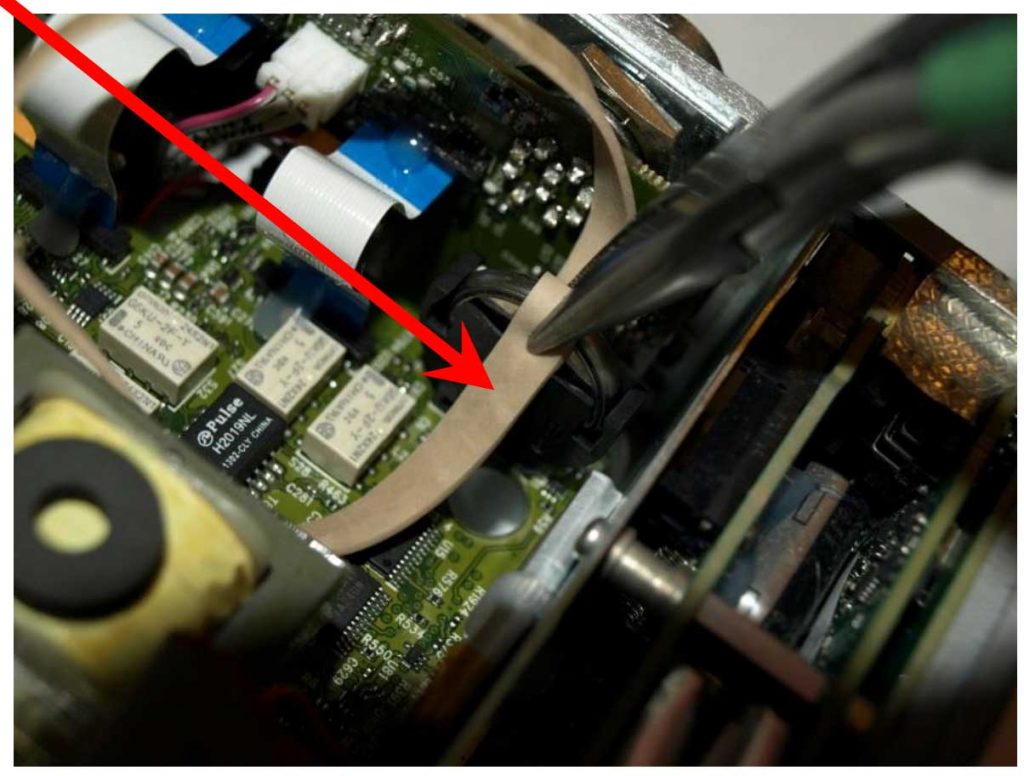
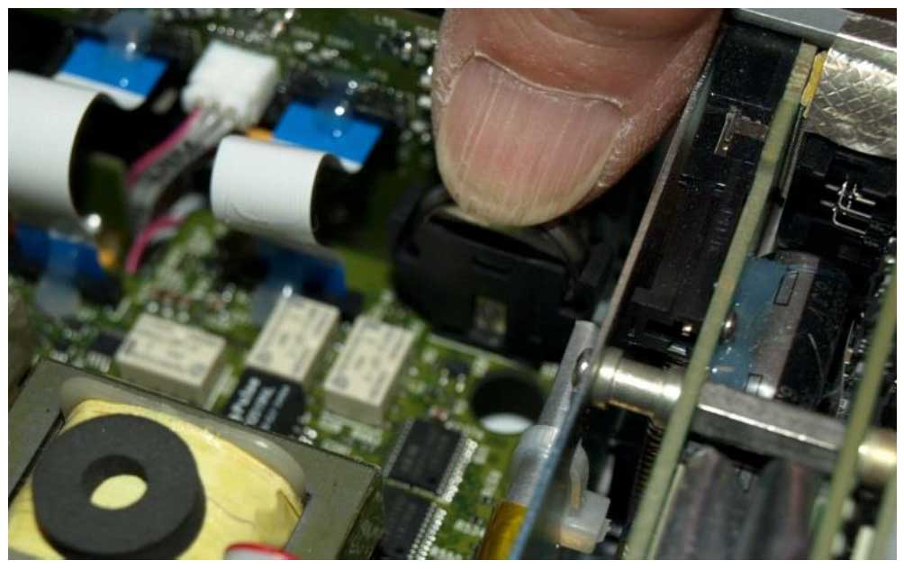
The RTC battery is a large coin-cell style in a holder just behind the front panel module. The coin-cell is very smooth and only a small portion is accessible, so it is very difficult to get a grip on it.
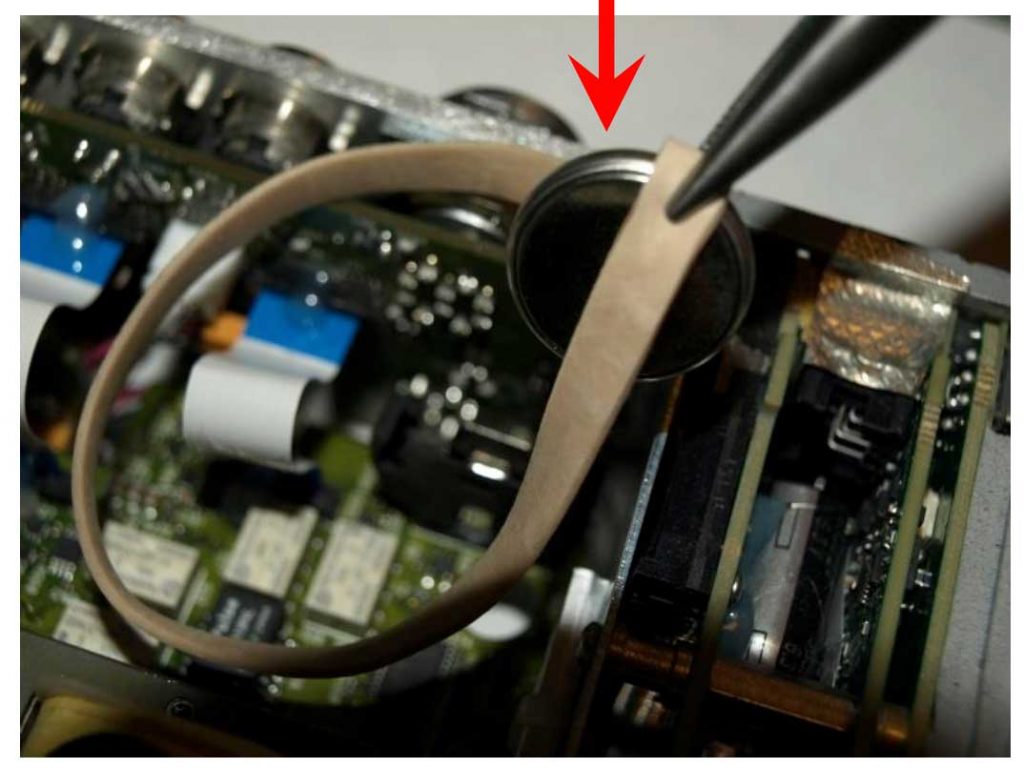
1. Do NOT use a bare plier as the metal jaw will short-circuit the battery. Instead, if you have a wide rubber band, lay it across the battery and then carefully grasp the edge of the battery.
2. With a gentle pull, it should slide out of the holder.
Remove RTC Battery (Alternate Method)
1. As an alternative to the plier, a piece of tape folded in half and stuck to the edges of the battery can be used. ‘Duct tape’ would be a good choice as it is quite sticky.
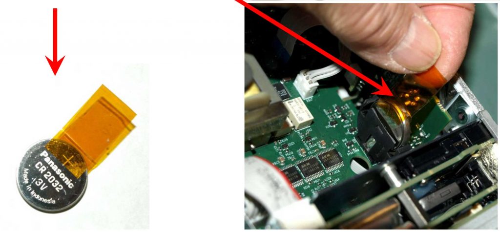
2. Pull up on tape to remove battery.
Install New Battery
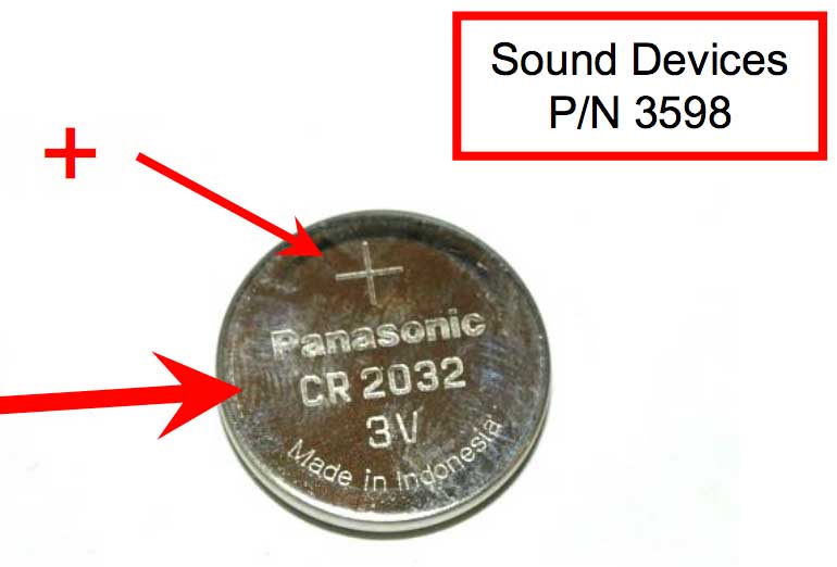
The 664 & 688 use a CR 2032 coin-cell. Notice the plus-sign (+) on one side of the cell.
1. Carefully place the new coin-cell into the opening of the holder.
CAUTION: Be absolutely certain that the side of the cell with the plus sign (+) is oriented toward the right end of the unit (opposite the side visible in this photo).
2. Press the cell straight down until it is fully seated in the holder.
Re-assemble
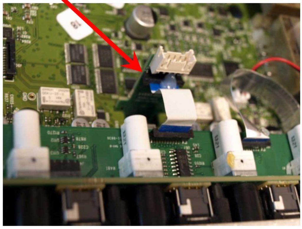
- Re-assemble the 664/688 by following the previous steps in reverse order. When placing the top panel in position, be sure the small, vertical PC board is indeed straight vertical (in the 688, it is plugged into a header connector which holds it secure). In the 664, if it’s not vertical, pull up slightly, move it to perfectly vertical and press it back down (the other end fits into a small recess in the bottom panel). When placing the top panel into position, this connector fits into a similar recess in the top panel.
- Some coaxing and repositioning may be necessary to get the top panel fully aligned with the top edges of the chassis. There is a channel around the perimeter of top panel that the chassis must fit into. Also check to be sure the media door pivot pins align with their mating holes in top and bottom panels.
- Once the unit is re-assembled, power it ON. Enter the Menu and set the correct date and time.