Replacing the Internal Hard Drive in 722 and 744T Recorders
The internal hard drive of the 722 and 744T can be removed and replaced for servicing damaged drives or to substitute drives of different capacity. In typical service conditions, Sound Devices recommends hard drive replacement once every three years.
Choosing a Replacement Hard Drive
The presently shipping version of the 722 and 744T are equipped with 2.5-inch Serial ATA (SATA) interface, 5400 RPM mechanical hard drives. Sound Devices has chosen the mechanism for maximum vibration and shock resistance. Most 2.5-inch mechanical hard drives conforming to the SATA specification can be substituted for the factory hard drive. Units produced before May 2009 used a parallel ATA (PATA/ IDE) interface and hard drive. The accessory product XL-SATA enables installation of SATA drives in these units. Replacing the original drives in 722 and 744T with higher RPM hard drives or solid state drives (SSD) provides little or no performance improvement compared to 5400 RPM hard drives. The FireWire bus in these recorders is the limitation on transfer speed. Additionally, higher speed hard drives may reduce battery run-time while the SSD’s have little effect on battery run-time, compared to a 5400 RPM hard drive. NOTE: The 722 and 744T were designed specifically for use with mechanical hard drives. While solid-state drives can be used as replacements, Sound Devices does not guarantee that the unit will operate to specification with an SSD substituted for a mechanical drive. Results may vary.
Drive Failures
Hard disk drives are mechanical devices and are susceptible to damage from physical shock. One type of physical shock, called operating shock, occurs when the disk is in operation. During operation, the drive head is typically over the drive platters reading and writing data. When a physical shock to the drive occurs during operation, the head and the platters can come into contact causing both components to be damaged. The second type of shock, called non-operating shock, occurs when the head is in the unloaded position, or not positioned over the platters. When a physical shock occurs in the non-operating state, the head can contact the ramp it is positioned over and damage the ability of the head to read and write data to the hard disk drive. All devices with hard drives are subject to damage from operating and non-operating shock. The mechanical construction of the 7-Series is designed to minimize the transmission of shock to the hard drive. The drive is isolated from the chassis using special shock-reducing closed-cell foam. This material increases the amount of shock the hard drive can withstand. Additional protection can be achieved by operating the unit in a carry case. If the recorder is used in applications subject to extreme motion, Sound Devices recommends recording to CompactFlash only. The hard drive will "park" its write heads to reduce the chance of failure. With all electrical devices, the higher the ambient temperature the shorter the device’s operational life. Therefore, take care to observe the specified temperature rating. There is also a risk from rapid temperature changes, which can create condensation inside the drive. This condensation can lead to the drive’s read/write heads adhering to the disk surfaces which will, in turn, stop the hard disk from rotating. Condensation tends to occur when the temperature inside the drive suddenly falls, for example, just after the unit is moved to a new location, or after operation is stopped in a cold environment. Sudden changes in temperature or air pressure can cause disk surface material to evaporate, which can also cause the head to adhere to the disk surface. This can happen when a hard disk drive is left unused for a long period of time.
Replacing the Internal Hard Drive
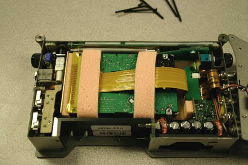
The internal hard drive is not intended to be a swappable, deliverable medium. Its multi-pin connector is not rated for repeated insertion and removal cycles and may be prone to breakage with repeated cycling. The hard drive is mounted to the bottom-side of the recorder’s chassis and is screwdriver accessible. The drive is “suspended” in the unit with a shock absorbing material and is attached to the main circuit board via a “flex board”. Since the unit’s high-density circuitry and tight construction require specific electronics knowledge, Sound Devices strongly recommends drive replacement be performed by a qualified technician using proper ESD precautions. Drive replacement done by a qualified technician has no warranty implications.
Steps
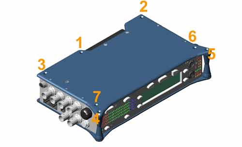
First, place recorder upside down on a steady flat surface. With a Phillips head screwdriver remove the screws on top.
Remove and Install screws in this order to avoid stripping:

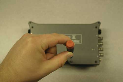
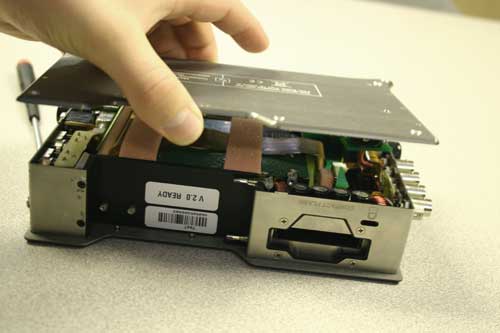
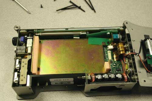
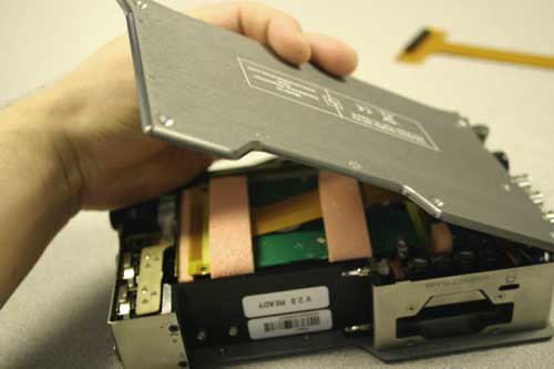
Gently remove the bottom panel. As you remove the bottom panel be careful of the internal AA battery wires as they will remain connected to the internal circuitry and the bottom panel.
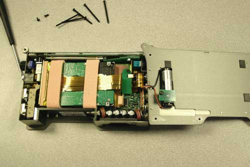
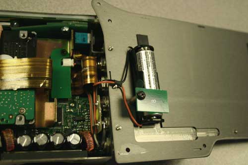
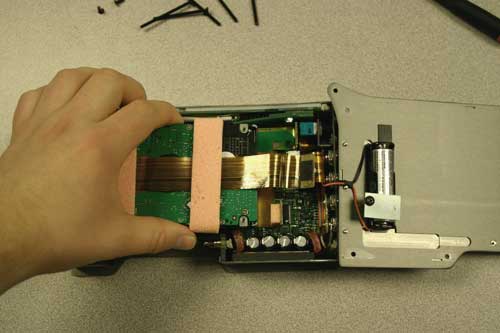
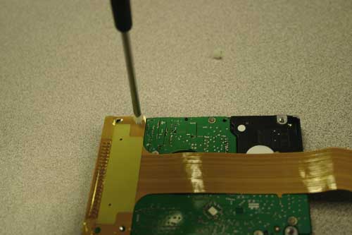
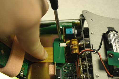
Loosen the screw of the small green circuit board holding down the hard drive ribbon cable.
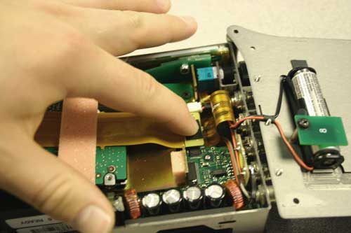
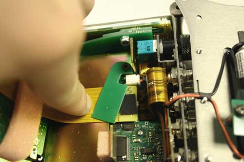
Swing the small green circuit board over while pressing down on the ribbon cable to avoid snagging.
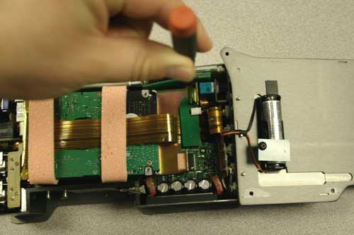
Carefully disconnect the the ribbon head mating connector from the circuit board.
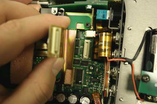
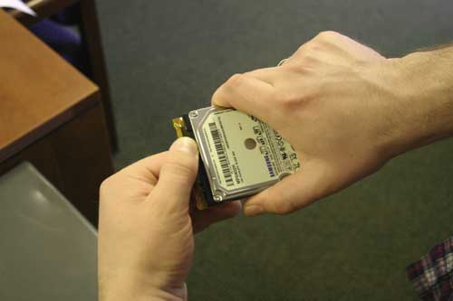
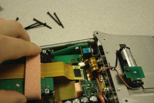
Remove the hard drive and attached ribbon cable from the recorder.
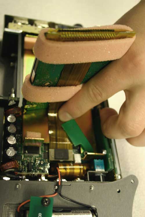
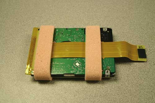
Place hard drive ribbon side up on a steady flat surface.
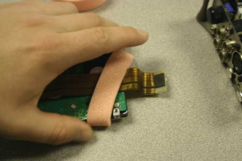
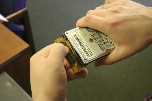
Remove the pink protective foam rings. Gently pull them down over the ribbon header connector.
Remove both plastic screws holding the ribbon cable to the hard drive using a Phillips head screwdriver.
Disconnect the hard drive from the ribbon cable header taking extreme care not to bend the pins of the hard drive.
Connect the new hard drive to the ribbon cable.

With the ribbon face up replace the two small plastic screws using a Phillips head screwdriver.
Replace both pink protective foam rings.

Connect the ribbon header mating connector to the circuit board connector.
While holding down the ribbon cable slide the small green circuit board piece over the ribbon header mating connector.
Using a Phillips head screwdriver tighten the green circuit board piece securing the ribbon mating connector to the circuit board.
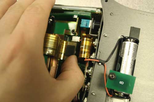
The hard drive should sit nicely in the chassis. Gently return the bottom panel to the all around panel.
Make sure all the tabs on the all around panel fit correctly in the bottom panel grooves.
Return the screws using a Phillips head screwdriver. This may require holding the bottom panel down firmly to the all around panel making sure that the tabs fit correctly.

Attention: Remove and Install screws in this order to avoid stripping.